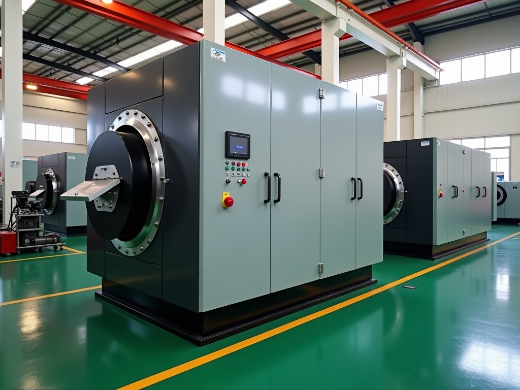
Oem Energy Efficient Cold Chamber Die Casting Machine Suppliers
Cold chamber die casting remains the preferred route for high‑melting‑point alloys such as aluminum, magnesium and copper‑based compositions. Energy‑efficient designs now integrate servo‑driven
OEM Energy‑Efficient Cold Chamber Die Casting Machines
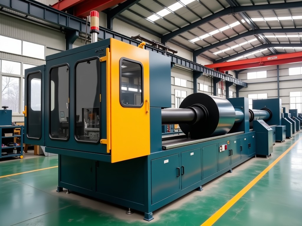
Cold chamber die casting remains the preferred route for high‑melting‑point alloys such as aluminum, magnesium and copper‑based compositions. Energy‑efficient designs now integrate servo‑driven injection, regenerative hydraulic circuits and advanced thermal management to lower specific energy consumption without sacrificing cycle speed or part integrity.
Core Technical Architecture
The machine frame is a welded box‑type structure stress‑relieved at 550 °C, providing a rigidity-to-weight ratio that limits frame deflection to <0.02 mm under full clamping load. A direct‑drive servo motor powers the injection plunger, delivering a programmable velocity profile from 0.1 m/s to 6 m/s with a repeatability of ±0.5 %. Hydraulic clamping uses a closed‑loop proportional valve paired with a pressure transducer, achieving a clamping force accuracy of ±1 % across the full 1,200–4,500 kN range.
Thermal insulation of the shot sleeve and gooseneck employs a ceramic‑fiber blanket (thermal conductivity 0.04 W/m·K) wrapped in a stainless‑steel jacket, reducing heat loss by approximately 30 % compared with conventional steel‑only designs. The melt‑holding furnace integrates a regenerative burner that recovers up to 45 % of exhaust enthalpy, feeding it back to the melt pool.
Energy‑Efficiency Features
- Servo‑driven injection eliminates constant‑speed hydraulic pump operation, cutting idle power draw by 55–70 %.
- Regenerative hydraulic circuit returns deceleration energy to the accumulator, reducing net hydraulic consumption up to 25 %.
- Variable‑frequency drive (VFD) on the furnace blower matches airflow to real‑time melt temperature, saving 12–18 % of burner fuel.
- Intelligent cycle‑time optimizer adjusts dwell and cooling phases based on part geometry, shaving 0.3–0.7 s per cycle without compromising solidification quality.
Combined, these measures typically lower specific energy consumption to 0.45–0.55 kWh/kg of cast alloy, a 20–30 % improvement over legacy cold‑chamber platforms of comparable tonnage.
Typical Specification Range
| Parameter | Typical Range | Customization |
|---|---|---|
| Clamping force | 1,200 – 4,500 kN | Adjustable in 100 kN steps |
| Maximum shot weight (Al) | 0.8 – 12 kg | Per cavity design |
| Injection velocity (max) | 6 m/s | Programmable profile |
| Cycle time (dry) | 3.5 – 7.0 s | Optimizer enabled |
| Specific energy consumption | 0.45 – 0.55 kWh/kg | Dependent on alloy & part |
| Control platform | Siemens S7‑1500 / Beckhoff TwinCAT | Customer‑specified PLC |
Values shown represent typical configurations for aluminum alloy series 3xx and 4xx. Exact figures are confirmed after reviewing part geometry, projected annual volume and utility infrastructure.
Application Fit
Automotive structural components — such as shock‑tower brackets and transmission housings — benefit from the rapid injection profile that minimizes porosity while the energy‑recovery system keeps per‑part cost competitive at volumes above 150 k units/year.
Electronics housings made from magnesium alloy AZ91D demand tight dimensional stability; the servo‑controlled injection reduces shot‑to‑shot weight variation to <0.3 %, supporting downstream CNC machining allowances of ≤0.1 mm.
Industrial pump casings in copper‑based alloys require high thermal conductivity and corrosion resistance. The regenerative furnace maintains melt temperature within ±2 °C, limiting oxide formation and ensuring consistent mechanical properties across long production runs.
Customization & Integration
Each OEM order begins with a joint engineering review covering:
- Cavity layout and projected shot weight per cavity.
- Available plant utilities (electric supply, compressed air, natural gas).
- Desired automation level — robot ladle, automatic die‑spray, in‑line vision inspection.
- Data‑exchange protocol (OPC UA, MQTT, PROFINET) for MES integration.
Tooling interfaces conform to NADCA standard 2‑hole pattern, but non‑standard bolt circles can be machined on request. The control cabinet is pre‑wired for remote I/O modules, allowing future expansion without rewiring.
Quality Assurance Philosophy
Every machine undergoes a three‑stage validation before shipment: (1) static load test at 110 % rated clamping force with strain‑gauge mapping, (2) dynamic injection repeatability test over 500 cycles recording velocity, pressure and position curves, (3) thermal soak of the furnace at target melt temperature for 8 h while monitoring energy draw. Acceptance criteria are documented in a test report supplied with the equipment.
Spare‑part kits — servo motor, proportional valve, ceramic insulation panels — are stocked for a minimum of five years. Preventive‑maintenance intervals are defined in the operation manual and can be synchronized with the customer’s CMMS.
Frequently Asked Questions
- Can the clamping force be upgraded after installation?
- Yes. The hydraulic power unit is sized with 15 % headroom; a higher‑rated cylinder and proportional valve can be swapped during a planned shutdown.
- What information is needed for a formal quotation?
- Part drawings (STEP/IGES), projected annual volume, alloy grade, available utility specs, and preferred control platform.
- Are the machines CE‑marked for European markets?
- All standard configurations comply with Machinery Directive 2006/42/EC and carry CE marking; documentation is provided on request.
- How is export packaging handled?
- Machines are secured on steel skids, wrapped in VCI film, and placed in fumigated wooden crates meeting ISPM‑15. Shock indicators are attached for transit monitoring.
- What is the typical lead time from order to delivery?
- 12–16 weeks for standard models; 18–24 weeks when custom automation or non‑standard tooling interfaces are required.
Ready to discuss your cold‑chamber die casting requirements?
Request a Technical Consultation | Download Datasheet