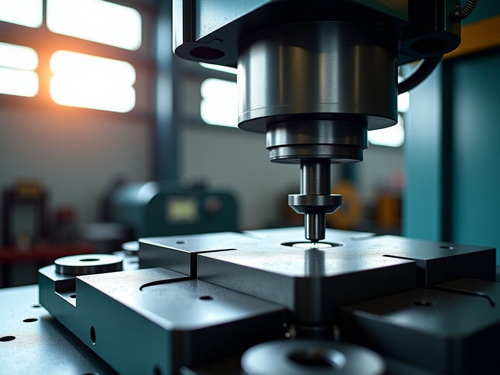
Oem Die Casting Machine Top Supplier
Selecting an OEM die casting machine supplier involves evaluating clamping force consistency, shot control precision, and thermal management across production cycles. This page outlines the technical
OEM Die Casting Machine Supply: Technical Capabilities & Integration Framework
Selecting an OEM die casting machine supplier involves evaluating clamping force consistency, shot control precision, and thermal management across production cycles. This page outlines the technical parameters, integration considerations, and quality frameworks that define reliable supply partnerships for high-pressure die casting (HPDC) and low-pressure die casting (LPDC) applications.
Information below reflects standard industrial configurations. Project-specific customizations — including platen dimensions, injection profiles, and automation interfaces — are engineered per application requirements.
Machine Classification & Clamping Force Range
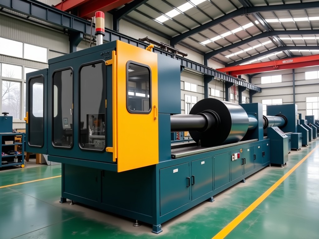
Die casting machines are categorized by locking force, which directly determines maximum projected casting area and achievable wall thickness. Cold-chamber machines handle aluminum, magnesium, and copper alloys; hot-chamber machines suit zinc, lead, and tin-based alloys. Clamping force ranges from 160 tons for small electronic housings to 4,400 tons for structural automotive components such as shock towers and subframe nodes.
Toggle-type clamping systems dominate above 800 tons due to faster dry cycles and lower hydraulic pressure requirements. Hydraulic direct-lock systems remain common below 500 tons where platen parallelism control simplifies die changeovers. Hybrid servo-hydraulic drives reduce energy consumption 30–45% versus fixed-displacement pumps by matching flow to cycle phase demand.
| Clamping Force (tons) | Typical Casting Weight (kg) | Platen Size (mm, H×V) | Tie Bar Spacing (mm, H×V) | Common Alloys |
|---|---|---|---|---|
| 160–350 | 0.1–1.5 | 420×420 to 650×650 | 280×280 to 450×450 | Zn, Mg, Al (small) |
| 400–800 | 1.5–6.0 | 720×720 to 1050×1050 | 500×500 to 710×710 | Al A380, ADC12, Mg AZ91D |
| 900–1600 | 6–18 | 1150×1150 to 1550×1550 | 800×800 to 1050×1050 | Al structural, Mg AM50/60 |
| 1800–3000 | 18–45 | 1700×1700 to 2200×2200 | 1150×1150 to 1450×1450 | Large Al structural, Cu alloys |
| 3200–4400 | 45–90+ | 2400×2400 to 3000×3000 | 1600×1600 to 2000×2000 | Giga-casting Al (A383, Silafont-36) |
Values represent typical ranges. Exact platen layouts, daylight openings, and ejection stroke lengths are configured per die design. Suppliers should provide GA drawings with T-slot patterns, ejector hole locations, and cooling channel interfaces before order confirmation.
Injection System Precision & Shot Control
Shot consistency governs porosity, dimensional stability, and surface finish. Modern machines employ accumulator-assisted injection with proportional valve control to achieve first-phase velocities of 0.1–0.3 m/s and second-phase (intensification) velocities of 1–10 m/s depending on alloy and gate design. Real-time pressure transducers on the shot sleeve enable closed-loop control with ±1.5% repeatability on peak pressure.
Multi-stage injection profiles — typically 5 to 8 programmable stages — allow tailored fill curves for complex geometries. Thin-wall automotive heat sink housings (<1.5 mm) demand fast second-phase transition (<15 ms) to avoid cold shuts. Thick structural nodes require slower fill with controlled intensification to minimize gas entrapment. Shot monitoring systems record velocity, pressure, and position at 1 kHz minimum; data exports via OPC UA or MQTT for SPC integration.
- Plunger diameters: 50–320 mm cold chamber; 25–120 mm hot chamber
- Intensification ratios: 8:1 to 25:1, selectable per alloy
- Accumulator volumes: 10–500 L nitrogen-charged, matched to shot volume
- Shot sleeve materials: H13 nitrided, beryllium-copper inserts for thermal fatigue resistance
- Vacuum system integration ports: standard KF40/KF50 flanges for evacuation to ≤20 mbar
Hot-chamber machines incorporate gooseneck heating zones with ±3°C PID control. Cold-chamber ladle systems offer automated pouring with weight-based metering (±0.5% accuracy) and inert gas shrouding for magnesium alloys. Ladle capacity typically 1.2× shot volume to maintain thermal stability.
Thermal Management & Die Temperature Control
Die temperature uniformity directly affects cycle time, soldering tendency, and dimensional repeatability. Machine-integrated thermal control units (TCUs) provide zone-specific heating and cooling with flow rates of 15–60 L/min per zone at 3–6 bar. Typical configurations include 8–24 independent zones for machines above 800 tons, with oil-based systems (max 180°C) for aluminum and water-based (max 95°C) for zinc/magnesium.
Infrared pyrometers or embedded thermocouples feed real-time die surface temperatures to the machine PLC. Adaptive cooling algorithms adjust flow per zone based on thermal gradient targets (typically ≤15°C across critical features). Pre-heating cycles bring dies to operating temperature in 20–40 minutes, reducing start-up scrap by 60–80% versus cold starts.
Spray systems use programmable reciprocating nozzles with air-atomized release agent delivery. Spray patterns, dwell times, and volumes are stored per die recipe. Closed-loop spray monitoring via flow sensors prevents dry cycles that cause soldering. Waste collection and filtration systems extend fluid life 3–5× versus open sump designs.
Automation Interfaces & Cell Integration
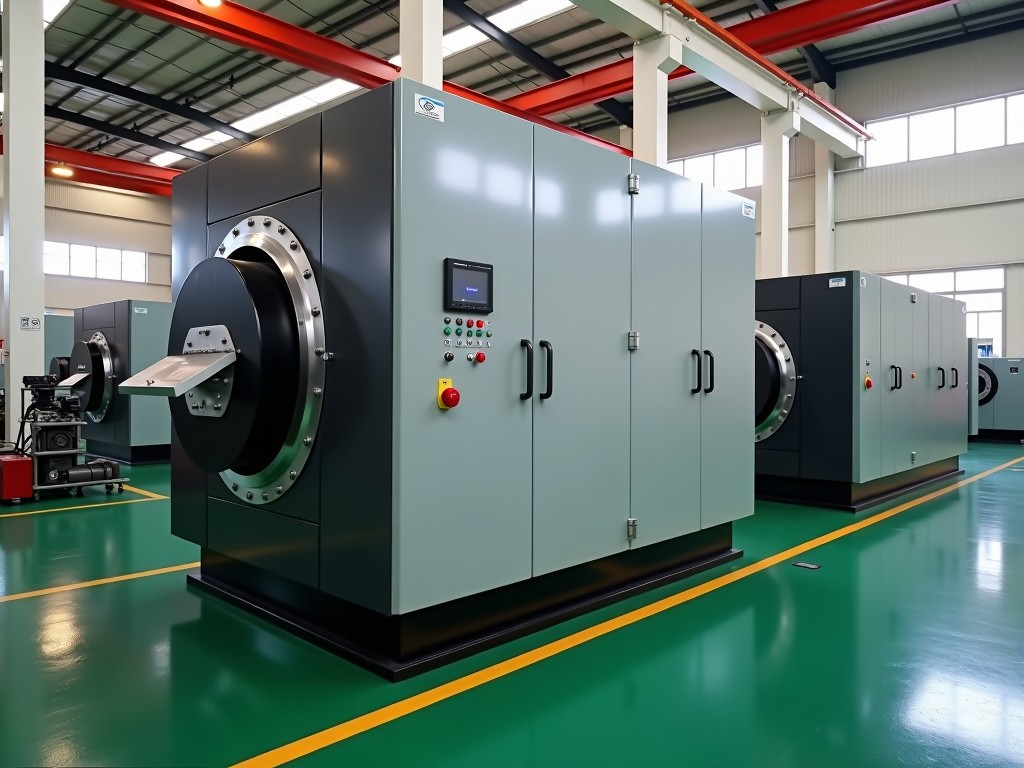
OEM machines ship with standardized automation interfaces to reduce cell integration engineering. Ethernet/IP, PROFINET, and EtherCAT fieldbuses connect to robot controllers, extractors, trimming presses, and vision inspection systems. Safety-rated I/O follows ISO 13849-1 PL d/e with dual-channel E-stop, light curtain muting, and guard-locking monitoring.
Mechanical interface plates on moving/fixed platens follow Euromap 67 / SPI AN-146 patterns for robot mounting. Ejector knockout rods accept standardized couplers for part extraction. Core slide hydraulic/pneumatic manifolds provide 4–12 circuits with pressure-rated quick disconnects (ISO 7241-1 Series B).
- Robot payload coordination: machine PLC shares real-time die position for synchronized extractor motion
- Die ID via RFID or barcode reader at load station enables automatic recipe selection
- Energy monitoring: per-cycle kWh logging for carbon footprint reporting
- Remote diagnostics: VPN-enabled PLC access for firmware updates and parameter backup
- MES integration tags: cycle count, shot data, alarm history, maintenance counters
Turnkey cell suppliers should confirm signal handshake timing during FAT (Factory Acceptance Test). Typical dry-cycle validation: 500 consecutive cycles with zero communication faults at target tact time.
Quality Assurance & Acceptance Protocols
Machine acceptance follows a three-phase protocol: geometric verification, dynamic performance testing, and production simulation. Geometric checks include platen parallelism under load (≤0.05 mm/m), tie bar stretch uniformity (±2%), and ejector plate alignment. Laser tracker or precision level measurements are documented with traceable calibration certificates.
Dynamic testing evaluates shot profile repeatability, clamping force build-up curves, and accumulator response times. Injection reproducibility is verified via 30 consecutive shots monitoring peak pressure, fill time, and biscuit thickness. Cpk ≥1.67 on critical parameters is the typical acceptance threshold.
Production simulation runs customer-provided dies (or representative test dies) for 8–24 hours. Key metrics: scrap rate, cycle time stability (±0.5 s), die temperature steady-state convergence, and spray consistency. First-article inspection reports (FAIR) per AS9102 or VDA 2 are generated for each critical dimension.
Customization Scope & Engineering Support
OEM supply agreements typically include application engineering support from die design review through production ramp. Machine modifications address specific process requirements:
- Extended daylight for tall dies or insert loading automation
- Reinforced platens for high-pressure squeeze casting (≥100 MPa intensification)
- Dual injection units for bi-metal or overmolding cycles
- Real-time X-ray inspection integration ports for in-line porosity screening
- Custom HMI screens for operator-guided changeover procedures
- Food-grade / medical-grade hydraulic fluid compatibility (HFC, synthetic esters)
Finite element analysis (FEA) of platen deflection under project-specific die loading is available for machines >1600 tons. Thermal simulation of die cooling/heating channels using customer CAD data optimizes TCU zone layout before steel cut. These services reduce first-article iteration cycles by 30–50%.
Maintenance Architecture & Lifecycle Support
Predictive maintenance frameworks reduce unplanned downtime. Condition monitoring sensors on hydraulic pumps (vibration, temperature, particle count), toggle bushings (wear via ultrasonic thickness), and shot end components (plunger tip wear via linear encoder) feed algorithms that forecast component life. Maintenance intervals shift from calendar-based to condition-based, extending fluid change intervals 2–3×.
Spare parts packages are tiered: critical (shot tips, seal kits, accumulator bladders), recommended (proportional valves, pressure transducers, heater bands), and strategic (toggle crossheads, tie bars, platens). Regional warehousing targets 24–48 hour delivery for critical items. Remote monitoring dashboards enable supplier engineers to diagnose faults before site visits.
Retrofit programs extend machine life 15–20 years. Common upgrades: servo-hydraulic pump replacement, PLC migration to current-generation controllers, safety system modernization to PL e, and energy recovery systems on accumulator dump circuits. ROI typically 18–36 months at 3-shift operation.
Commercial Framework & Project Execution
Quotation requires: annual volume forecast, casting weight range, alloy specifications, cycle time target, automation scope (standalone vs. integrated cell), and facility utilities (power, water, compressed air, gas). Lead times: 20–28 weeks for standard machines 400–1600 tons; 32–48 weeks for >2000 tons or custom configurations. Engineering kickoff occurs 4–6 weeks after PO.
Payment structures typically follow milestone gates: 30% at PO, 30% at design freeze, 30% at FAT completion, 10% at SAT (Site Acceptance Test) sign-off. Performance guarantees cover shot repeatability, clamping force accuracy, dry cycle time, and energy consumption per agreed test protocol. Warranty: 12 months from SAT or 18 months from shipment, whichever occurs first.
Training programs cover operator, maintenance, and process engineer tracks. Documentation package includes: electrical/hydraulic schematics (native CAD format), PLC source code (structured text), maintenance manuals with BOM, safety validation reports, and spare parts catalog with cross-references.
Define your machine specification with application engineers
Submit casting geometry, volume targets, and process requirements for a detailed technical proposal including cycle time simulation and cell layout.
Request Technical Consultation