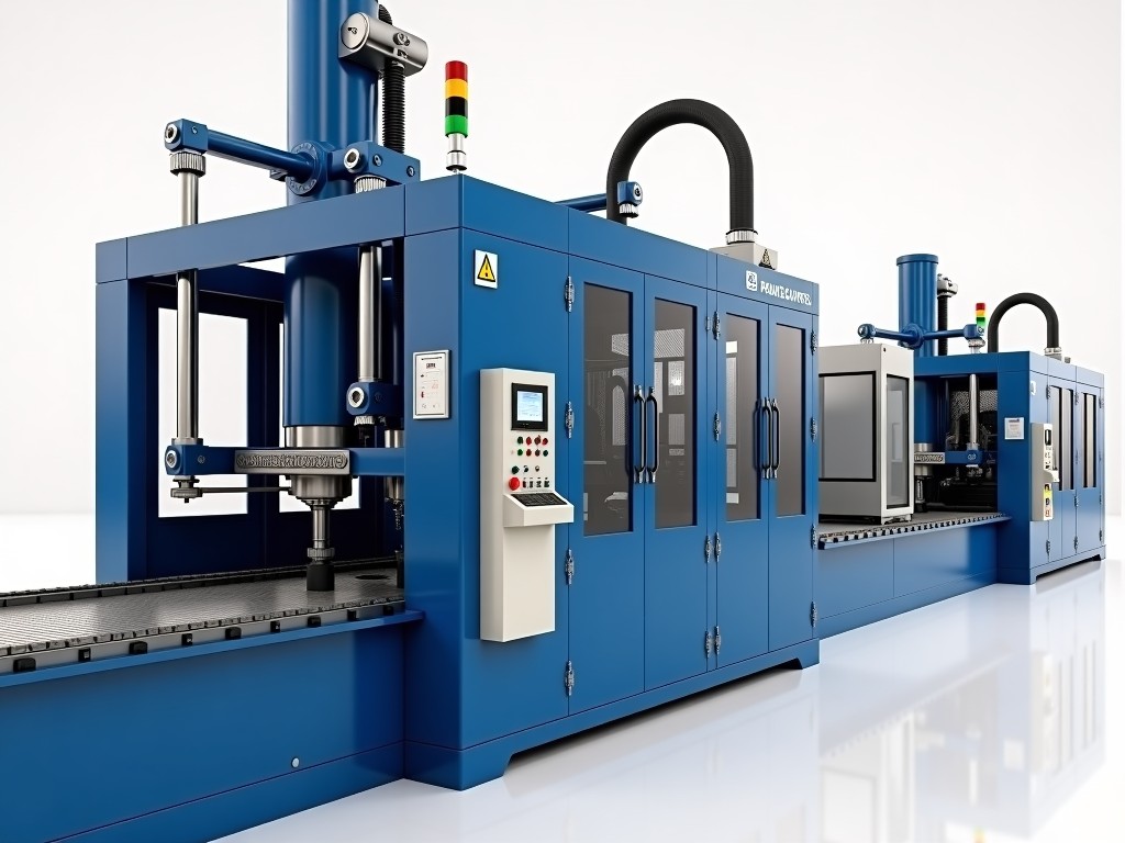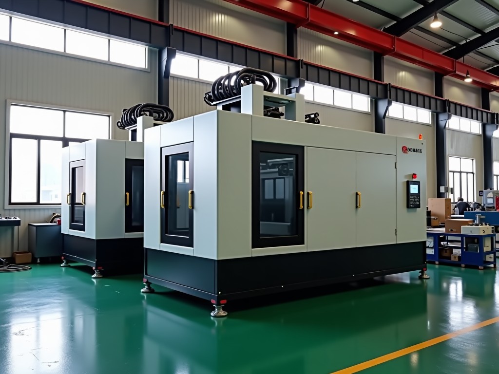
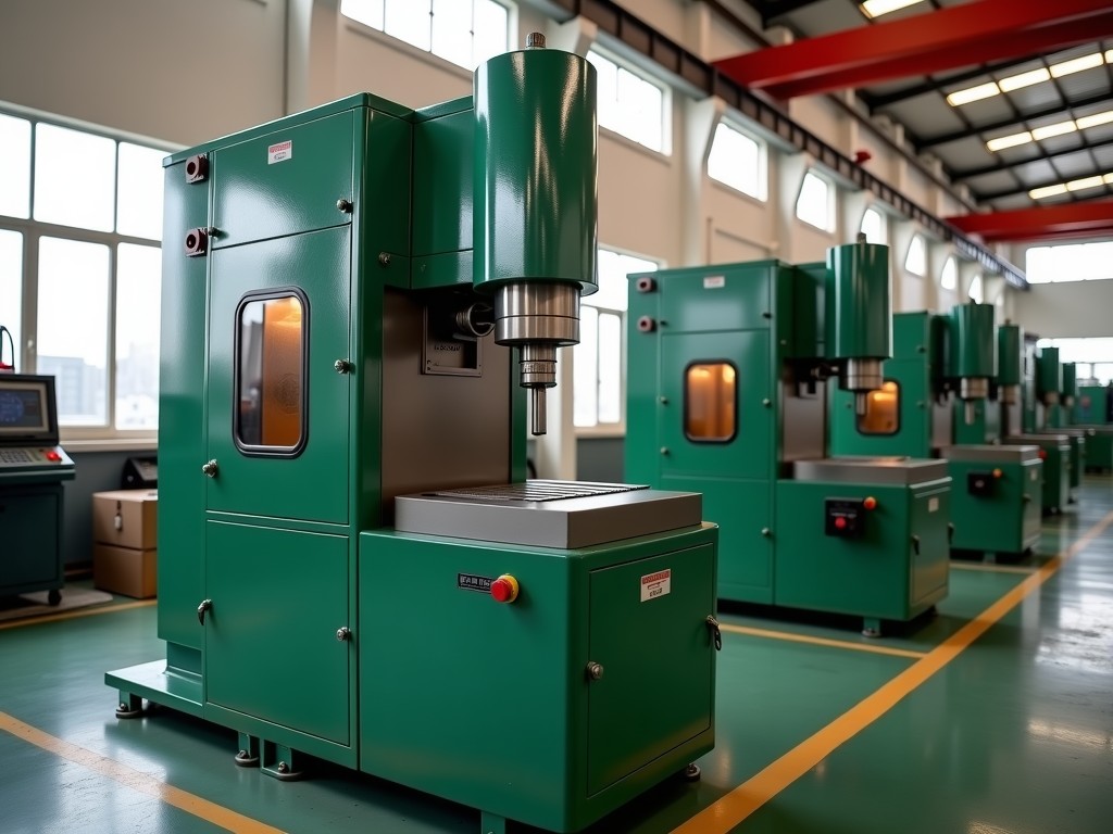
Custom Hot Chamber Die Casting Machine Manufacturer
Hot‑chamber die casting keeps the molten metal reservoir immersed in a heated gooseneck, which eliminates the need for a separate ladle and shortens the injection cycle. This configuration is
Custom Hot Chamber Die Casting Machine Manufacturer
Hot‑chamber die casting keeps the molten metal reservoir immersed in a heated gooseneck, which eliminates the need for a separate ladle and shortens the injection cycle. This configuration is standard for low‑melting‑point alloys such as zinc, magnesium, and certain lead‑based compositions.
A custom machine is built around the specific part geometry, annual volume, and alloy chemistry of each project. Rather than adapting a standard catalog unit, the clamp frame, shot sleeve, and control architecture are sized from the ground up to match the required shot weight and cycle time.
Typical Specification Range (Customizable)
| Parameter | Typical Range | Customization Note |
|---|---|---|
| Clamping Force | 150 – 2 500 kN | Scaled to projected part area and safety factor |
| Shot Weight (Zn alloy) | 0.2 – 12 kg | Adjusted by plunger diameter and stroke |
| Maximum Injection Pressure | 30 – 120 MPa | Selected per alloy viscosity and wall thickness |
| Cycle Time (dry cycle) | 1.5 – 6 s | Optimized through servo‑driven plunger and fast‑acting valves |
| Control System | PLC + HMI (Siemens, Mitsubishi, or Beckhoff) | Open‑protocol options for MES integration |
| Main Power Supply | 380 V / 50 Hz / 3‑phase (custom voltages available) | Transformers supplied for regional standards |
Key Customization Levers
Engineers typically adjust the following levers to align machine performance with part requirements:
- Plunger diameter and stroke length – directly set shot volume and peak pressure.
- Gooseneck material and heating zone layout – influences melt stability for magnesium versus zinc.
- Clamp frame stiffness – finite‑element analysis confirms deflection < 0.02 mm under full load.
- Servo‑hydraulic or all‑electric injection drive – trade‑off between energy consumption and response speed.
- Automation interface – robot extractor, conveyor, or vision‑guided part handling.
Alloy Compatibility & Process Implications
Zinc alloys (e.g., Zamak 3, Zamak 5) dominate hot‑chamber production because their melting point (~380 °C) allows a simple heated gooseneck. Magnesium alloys (AZ91D, AM60B) require a higher furnace temperature (~650 °C) and a protective inert atmosphere to prevent oxidation; the machine’s sealing system and gas‑purge circuit are therefore specified per alloy. Lead‑based bearing alloys demand corrosion‑resistant gooseneck liners (typically ceramic‑coated steel) and a dedicated fume extraction manifold.
When the project calls for multi‑alloy flexibility, the furnace can be equipped with interchangeable crucible inserts and a rapid‑change heating cartridge, reducing alloy switch‑over to under 30 minutes.
Industries & Application Rationale
Automotive interior components (door handles, bracket housings) benefit from the high‑speed cycle and tight dimensional repeatability of a custom hot‑chamber press, allowing > 1 M parts per year with a single cavity tool.
Consumer‑electronics enclosures (smartphone frames, connector housings) exploit the excellent surface finish of zinc die castings, eliminating secondary machining on critical cosmetic surfaces.
Industrial hardware (gear blanks, valve bodies) often requires magnesium for weight reduction; the machine’s inert‑gas purge and precise temperature control keep porosity below 0.2 % volume, meeting pressure‑tight specifications.
Manufacturing & Quality Assurance
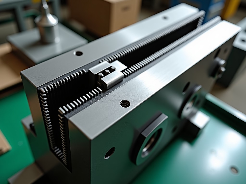
Frames are machined from normalized 42CrMo4 steel, heat‑treated to 280–320 HB, and stress‑relieved after welding. Critical bearing surfaces receive a 0.02 mm grind finish to guarantee repeatable clamp alignment.
Each machine undergoes a three‑stage acceptance test: (1) dry‑cycle speed and repeatability verification, (2) hot‑run with the target alloy to confirm melt temperature stability ±2 °C, (3) dimensional inspection of a first‑article casting using a coordinate‑measuring machine (CMM) to validate cavity fill and shrinkage compensation.
Inspection reports, material certificates (EN 10204 3.1), and PLC program backups are shipped with the equipment. Optional on‑site commissioning includes operator training and a 12‑month preventive‑maintenance schedule.
Frequently Asked Questions
- Can the machine dimensions be tailored to fit an existing production line? Yes – overall footprint, column height, and service‑access clearance are defined during the layout study.
- What information is needed for a quotation? Part drawing or 3‑D model, annual volume, alloy grade, required cycle time, and any automation interfaces.
- Which alloys can be processed on the same platform? Zinc, magnesium, and lead‑based alloys are standard; other low‑melting alloys are evaluated case by case.
- How is quality inspected before shipment? Dry‑cycle repeatability, hot‑run temperature stability, and first‑article CMM inspection are documented in the acceptance report.
- What packaging methods are used for export? Machines are secured on steel skids, vacuum‑wrapped with desiccant, and braced in a 20‑ft or 40‑ft container per ISPM‑15.
- What is the typical production lead time? 12–18 weeks from order confirmation for a fully customized unit; standard modules can reduce this to 8 weeks.
Next Steps
A technical discussion clarifies the exact clamp force, shot profile, and control architecture before any commitment. Sharing a part model and volume forecast enables a preliminary layout and budget estimate within 48 hours.