Custom Die Casting Machine For Electronics Led Housing Factory
Die casting remains the most cost‑effective route to high‑volume, thin‑wall aluminum or zinc alloy housings for LED modules. A machine tuned to the dimensional tolerances and surface‑finish
Custom Die Casting Machine for Electronics LED Housing Factory
Die casting remains the most cost‑effective route to high‑volume, thin‑wall aluminum or zinc alloy housings for LED modules. A machine tuned to the dimensional tolerances and surface‑finish requirements of lighting components reduces secondary machining and scrap.
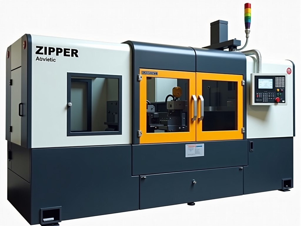
Our platform starts from a proven cold‑chamber architecture and adds a modular shot‑control system, rapid‑change mold interface, and integrated process monitoring. Each subsystem can be selected or omitted based on the target alloy, cycle‑time goal, and factory layout.
Key Technical Specifications
| Parameter | Typical Value / Range | Customization Note |
|---|---|---|
| Clamping force | 1,200–2,500 kN | Selectable in 100 kN increments |
| Shot weight (Al alloy) | 0.8–3.5 kg | Adjusted by plunger diameter |
| Maximum injection pressure | 1,200 bar | Higher pressure available on request |
| Cycle time (dry cycle) | 2.5–4.0 s | Dependent on mold cooling design |
| Mold opening stroke | 350–600 mm | Extended stroke for deep‑draw housings |
| Control system | Siemens S7‑1500 / Beckhoff TwinCAT | Protocol‑agnostic OPC‑UA interface |
Modular Customization Options
Because LED housing designs vary from ultra‑thin heat‑sink fins to integrated lens mounts, the machine can be configured with any combination of the following modules:
- Quick‑change mold carrier with pneumatic locking – reduces changeover to under 3 minutes.
- Vacuum‑assisted injection for porosity‑critical zinc alloys.
- In‑line laser trim station for flash removal without secondary handling.
- Integrated thermal imaging for real‑time mold temperature mapping.
- Automated part ejection with robotic gripper synchronized to cycle.
- Energy‑recovery hydraulic accumulator to lower peak power demand.
Each module is supplied with its own PLC function block, allowing the plant’s MES to enable or disable features per production order without mechanical re‑work.
Why This Machine Fits LED Housing Production
LED housings demand tight wall‑thickness control (±0.05 mm) and a surface finish that accepts anodizing or powder coating without additional polishing. The shot‑control system maintains a repeatable pressure profile within ±2 % across the entire shot, which directly translates to consistent wall thickness.
The rapid‑change mold carrier supports multi‑cavity tools up to 8 cavities, enabling a single press to meet annual volumes of 5 million units while keeping floor space under 30 m². The integrated thermal imaging prevents hot‑spot formation that would otherwise cause solder‑joint failures in the final lamp assembly.
Quality Assurance & Process Control
Every unit ships with a calibrated pressure transducer traceable to ISO 17025. The control software logs injection pressure, plunger velocity, and mold temperature at 1 kHz, storing the last 10 000 cycles for statistical process control.
Optional in‑process X‑ray inspection can be mounted on the ejection side, providing real‑time porosity detection for safety‑critical automotive lighting programs.
Frequently Asked Questions
Can the clamping force be increased after installation?
The frame is designed with bolt‑on reinforcement plates; a 15 % uplift is achievable by adding the optional high‑strength tie‑bars and recalibrating the hydraulic circuit.
What information is needed for a formal quotation?
Target alloy, annual volume, cavity count, required cycle time, available floor space, and preferred control platform. A CAD model of the housing helps confirm mold‑carrier compatibility.
Which mold materials are supported?
Standard H13 tool steel, premium 8407, and copper‑alloy inserts for rapid heat extraction. The machine’s cooling circuit accommodates up to 12 independent zones.
How is shipment protection handled for export?
Machines are bolted to a steel skid, wrapped in VCI film, and placed in a sealed wooden crate with shock‑monitoring indicators. Custom crating dimensions are provided per Incoterm.
What is the typical lead time from order to commissioning?
12–16 weeks for a standard configuration; add 3–4 weeks per custom module. A detailed project schedule is issued after the technical review meeting.
Next Steps
A short technical discussion clarifies the exact module set and confirms the commercial terms. Our application engineers can run a virtual cycle simulation using your 3‑D housing data to validate cycle‑time targets before any hardware commitment.
Request a quotation | Download datasheet | Speak with an engineer