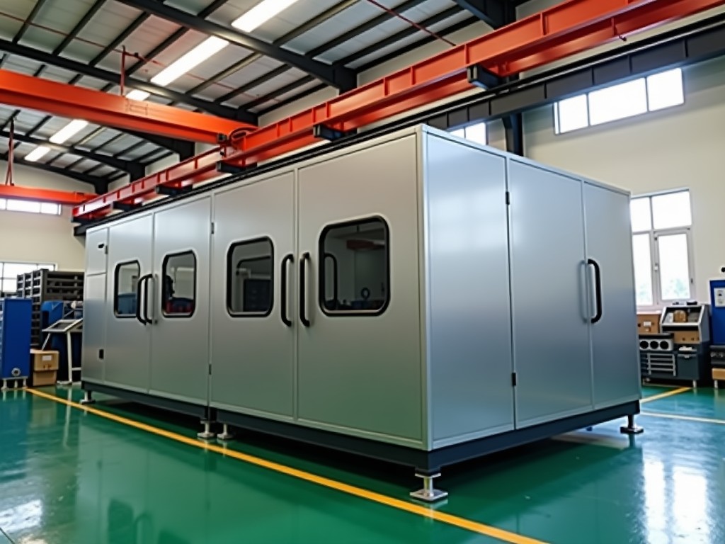
Custom Cold Chamber Die Casting Machine Supplier
Cold chamber die casting remains the primary process for high-volume production of aluminum, magnesium, and copper-based alloy components requiring tight dimensional control and structural integrity.
Custom Cold Chamber Die Casting Machine Supplier
Cold chamber die casting remains the primary process for high-volume production of aluminum, magnesium, and copper-based alloy components requiring tight dimensional control and structural integrity. Unlike hot chamber systems where the injection mechanism resides in the melt, cold chamber machines separate the melting furnace from the shot sleeve, eliminating continuous thermal exposure to the plunger and sleeve assembly. This architectural distinction enables processing of alloys with melting points above 600°C while reducing iron pickup and extending consumable life.
Standard catalog machines address common tonnage bands and plate sizes, but production environments increasingly demand integration with automated cells, specific shot profiles for thin-wall or structural castings, and compliance with regional safety standards. A custom supplier adapts the base platform — frame rigidity, tie-bar spacing, platen dimensions, injection unit geometry, and control architecture — to match the casting envelope, cycle time targets, and peripheral equipment interface requirements of each project.
Technical Specification Framework
The following table outlines the typical parameter ranges available for customization. Final values are determined during the engineering review phase based on casting geometry, alloy selection, annual volume, and facility constraints.
| Parameter | Typical Customizable Range | Engineering Consideration |
|---|---|---|
| Clamping Force | 1,200 kN – 45,000 kN (120 – 4,500 ton) | Scaled to projected area × specific casting pressure; frame deflection < 0.15 mm/m |
| Tie-Bar Spacing (H × V) | 450 × 450 mm – 2,200 × 2,200 mm | Dictates maximum die footprint; affects machine footprint and foundation loads |
| Platen Size (H × V) | 650 × 650 mm – 3,000 × 3,000 mm | Must accommodate die shoes, ejector box, and cooling manifold clearance |
| Stroke Opening | 350 mm – 3,500 mm | Determines part extraction clearance; impacts cycle time on tall castings |
| Injection Force (Intensified) | 180 kN – 6,500 kN | Matched to gate area × intensification pressure; affects filling velocity capability |
| Plunger Diameter | 50 mm – 320 mm | Selected for 45–65% fill ratio; influences metal pressure and sleeve wear rate |
| Shot Position Count | 1 to 4 positions (horizontal/vertical) | Multi-position enables family molds or insert loading without die change |
| Dry Cycle Time (EUROMAP 6) | 1.8 s – 18 s (size-dependent) | Optimized toggle kinematics and accumulator sizing reduce non-productive time |
| Control System | Siemens S7-1500 / Beckhoff CX / Custom PLC + HMI | Determines shot profile resolution, data logging depth, and Industry 4.0 connectivity |
| Safety Standard Compliance | CE (MD 2006/42/EC), ANSI B152.1, GB/T 22530, NR-12 | Region-specific guarding, light curtains, two-hand control, and validation documentation |
Customization Domains
Injection Unit Architecture
The injection unit defines metal delivery precision. Customization begins with selecting between horizontal and vertical shot configurations — horizontal suits conventional ladling and robotic pourers, while vertical enables shorter metal paths for reactive alloys like magnesium where oxidation control is critical. Plunger tip material (beryllium copper, tool steel, or ceramic-coated) and sleeve cooling circuit design (conformal vs. drilled) are matched to alloy chemistry and shot weight to minimize soldering and thermal fatigue cracking.
Shot profile resolution is governed by the servo-valve or proportional-valve response time and the control loop update rate. High-end custom machines implement 1 kHz closed-loop pressure/velocity control with multi-stage profiles: slow fill for runner/gate systems, fast fill for cavity, and programmable intensification ramp. This level of control reduces gas entrapment in structural castings and enables wall thicknesses below 1.5 mm in aluminum alloys.
Clamp Unit Kinematics and Rigidity
Toggle geometry (double, triple, or five-point) is selected based on the force-stroke curve required. Five-point toggles provide near-constant force over the final 15% of stroke, beneficial for thin-wall parts where flash control depends on consistent clamp pressure during intensification. Tie-bar pre-tensioning systems — hydraulic or mechanical — maintain parallelism under thermal cycling. For machines above 2,500 ton, finite element analysis validates frame deflection under maximum lock-up force, ensuring die separation remains below 0.05 mm at the parting line center.
Automation Interface and Cell Integration
Modern custom machines ship with standardized mechanical and electrical interfaces for extractors, spray robots, insert loaders, and part conveyors. Mechanical interfaces include T-slotted or drilled patterns on moving/fixed platens per EUROMAP 18/67, plus dedicated mounting faces for third-party extractor beams. Electrically, a dedicated automation cabinet provides 24 VDC I/O, PROFINET/EtherNet/IP fieldbus, and safety-rated E-stop chains. Software handshakes follow EUROMAP 77/82.1 for spray/extractor synchronization and EUROMAP 83 for traceability data exchange with MES.
Thermal Management and Furnace Integration
Cold chamber efficiency depends on consistent metal temperature at the shot sleeve. Custom suppliers coordinate with furnace vendors (or supply proprietary holding furnaces) to define launder geometry, transfer ladle capacity, and pour rate. Automated ladle systems with tilt control ±2° and pour time profiling reduce temperature drop to < 8°C between furnace and sleeve. For magnesium, inert gas shrouding (SF₆-free cover gas or Novec 612) integrates into the pour envelope and shot sleeve purge circuit.
Application-Specific Engineering Rationale
Automotive structural components — shock towers, subframe nodes, battery housings — require machines capable of 400+ bar intensification pressure with shot control resolution below 0.5 ms. The custom frame design incorporates extended tie-bar spacing to accommodate multi-cavity dies with slide cores, while the injection unit delivers fill velocities up to 10 m/s for thin sections. Real-time cavity pressure feedback (via die-integrated sensors) closes the loop on intensification timing, reducing scrap from porosity by 15–25% compared to open-loop profiles.
Electronics housings and 5G base station components prioritize surface finish and dimensional stability over structural load. Here, the customization focuses on shot-end thermal stability: ceramic-coated sleeves, oil-temperature control within ±1°C, and low-inertia servo-driven injection for repeatable first-stage fill. Machines configured for these applications often feature reduced clamp stroke and compact footprint to maximize cells per factory floor area.
Heavy industrial castings — motor housings, pump bodies, valve manifolds — shift emphasis to clamp rigidity and large shot volumes. Custom machines in the 3,000–4,500 ton range incorporate reinforced platen ribbing, oversized tie-bars (Ø280–360 mm), and dual-pump hydraulic systems with 400+ L/min accumulator capacity for rapid intensification. The shot end accommodates plunger diameters up to 320 mm with shot weights exceeding 40 kg per cavity.
Manufacturing and Quality Assurance
Frame weldments undergo stress relief (vibratory or thermal at 550–600°C) before final machining. Critical surfaces — platen faces, tie-bar bores, toggle pin holes — are machined in a single setup on large-format five-axis boring mills to guarantee parallelism within 0.02 mm/m. Tie-bars are rolled-thread after heat treatment to 1,000–1,200 MPa tensile strength, with 100% ultrasonic inspection per ASTM A388.
Hydraulic systems are assembled in a class 7 cleanroom environment. Proportional valves and servo-valves undergo dynamic response testing at 100% rated flow before installation. Accumulators are charged and pressure-tested to 1.43× working pressure. Every machine completes a 4-hour hot run with instrumented die (strain gauges on tie-bars, pressure transducers in shot sleeve, LVDTs on toggle crosshead) to validate clamp force linearity, injection repeatability (CpK > 1.33 on gate velocity), and thermal equilibrium.
Control software undergoes hardware-in-the-loop simulation with virtual die models before commissioning. Safety functions (guard monitoring, two-hand control, pressure relief validation) are verified per ISO 13849-1 PL d or e depending on risk assessment. Documentation package includes electrical schematics (EPLAN), hydraulic diagrams (ISO 1219), PLC source code (structured text), and a digital twin model for offline programming.
Project Execution Workflow
- Requirement Capture: Casting drawings, annual volume, alloy spec, cycle time target, facility layout, utility availability, regional compliance needs.
- Concept Proposal: 3D general arrangement, clamp/injection sizing calculations, automation interface definition, preliminary foundation loads, budget estimate (±15%).
- Design Freeze & Engineering: FEA validation, BOM finalization, long-lead procurement (servo-valves, PLC, tie-bars), sub-supplier coordination.
- Manufacturing & Assembly: 16–28 weeks depending on tonnage and customization depth; weekly progress reports with photos.
- Factory Acceptance Test (FAT): Customer-witnessed run per agreed protocol; dry cycle, hot run with customer alloy (if feasible), safety validation, data handover.
- Shipment, Installation, SAT: Sea/land transport with vibration monitoring; on-site leveling, utility connection, SAT with production die, operator training, handover of spare parts kit and maintenance schedules.
Frequently Asked Technical Questions
What information is required to initiate a quotation?
Minimum: 2D/3D casting drawing with projected area and wall thickness distribution, alloy designation, annual volume, target cycle time, number of cavities, facility ceiling height and floor load capacity, destination country (for compliance), and preferred control platform. Furnace and automation scope (supplier scope vs. buyer scope) should be clarified early.
Can the machine accommodate multiple die sizes on a single platform?
Yes. Quick-change platen systems (hydraulic or mechanical clamping) allow die changes under 15 minutes for dies within the same footprint class. For wider size ranges, adjustable tie-bar spacing or modular platen inserts are available. The control system stores die-specific recipes including shot profile, clamp force, spray sequence, and extractor path.
How is shot end wear managed for high-volume aluminum production?
Sleeve life typically ranges 80,000–150,000 shots for ADC12/A380 depending on cooling efficiency and plunger tip material. Custom machines incorporate sleeve wear monitoring via linear position feedback on the plunger tip (inductive or magnetostrictive). Predictive maintenance alerts trigger at 80% of expected life. Optional automated sleeve puller reduces changeover to < 30 minutes.
What is the typical lead time for a 2,500 ton custom machine?
22–28 weeks from design freeze to FAT, assuming standard servo-valve and PLC availability. Long-lead items (custom frame casting/forging, large tie-bars, main cylinders) are ordered upon receipt of deposit. Expedited schedules (18 weeks) are possible with parallel engineering and premium freight for bought-out components.
How are export shipments protected for sea transport?
Machines are drained of hydraulic oil, nitrogen-purged, and sealed with VCI (volatile corrosion inhibitor) film. Critical machined surfaces receive rust preventive coating (Mobilarma 524 or equivalent). Components are braced in 40' HC or flat-rack containers with shock/tilt indicators. Humidity data loggers travel with the shipment. Re-commissioning oil and filter kits ship in the same container.
What spare parts and training are included?
Standard commissioning kit includes: proportional/servo valve spare, pressure transducer set, filter elements (6 months), seal kits for main cylinders and accumulator, plunger tip set (3 pcs), sleeve thermocouples, and safety relay. Training covers 3 days on-site: operation, maintenance, shot profile optimization, and basic PLC diagnostics. Advanced process engineering support available separately.
Request a Technical Consultation
Every cold chamber die casting project has unique constraints — alloy behavior, part geometry, cycle economics, facility integration. A 30-minute technical call with our application engineers clarifies the specification path and identifies cost drivers before formal quotation.
Schedule Technical Review