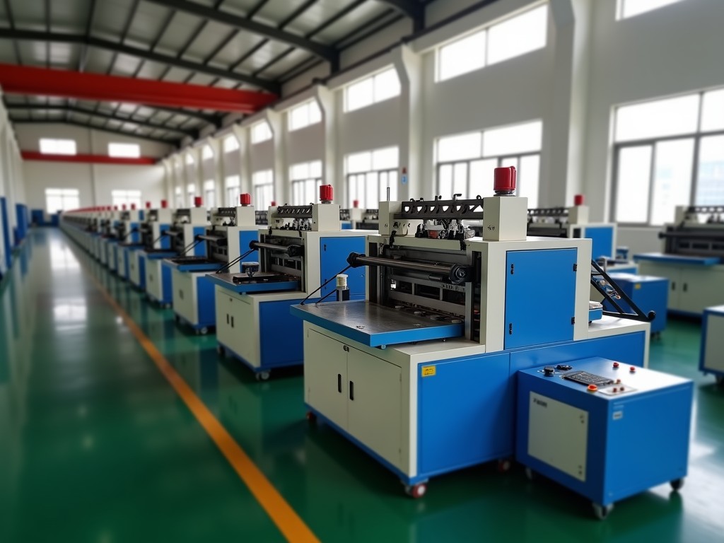
China Zipper Slider Making Machine Company
Engineered for high-volume zipper component manufacturing. Our machines integrate die-casting, stamping, and automated assembly into configurable production lines that deliver dimensional consistency
China Zipper Slider Making Machine Company — Precision Die-Casting & Stamping Equipment for Slider Production
Engineered for high-volume zipper component manufacturing. Our machines integrate die-casting, stamping, and automated assembly into configurable production lines that deliver dimensional consistency across zinc alloy, brass, and aluminum slider bodies.
Technical Overview: How Slider Making Machines Work
A zipper slider making machine transforms raw metal — typically zinc alloy (Zamak 3 or Zamak 5), brass (C3604), or aluminum (ADC12) — into finished slider components through a sequence of forming, trimming, and assembly stations. The core process divides into three phases: body formation, puller attachment, and final inspection.
Body formation uses either hot-chamber die-casting for zinc alloys or cold-chamber for brass and aluminum. Molten metal injects into multi-cavity molds at 30–60 MPa, producing net-shape bodies with draft angles of 0.5–1.5° and wall thicknesses of 1.2–2.5 mm. Cycle times range from 3 to 8 seconds per shot depending on cavity count and cooling design.
Stamping stations handle puller tabs, locking springs, and reinforcement plates. Progressive dies feed coil stock at 60–120 strokes per minute, maintaining ±0.03 mm positional accuracy. Spring tempering occurs inline at 350–420°C for 8–12 minutes to achieve 1,200–1,500 MPa tensile strength.
Machine Configurations & Typical Specifications
We supply three primary machine families, each scalable from standalone units to fully automated cells. Selection depends on annual volume, material mix, and slider complexity (standard, reversible, auto-lock, double-pull).
| Parameter | Die-Casting Line (Zinc) | Stamping & Assembly Line | Integrated Turnkey Cell |
|---|---|---|---|
| Annual Output (sliders) | 50M – 200M | 80M – 300M | 100M – 500M+ |
| Cavities per Mold | 4 – 16 (standard) | N/A | 8 – 24 |
| Clamping Force | 80 – 280 ton | N/A | 120 – 400 ton |
| Stamping Speed | N/A | 60 – 150 SPM | 80 – 180 SPM |
| Dimensional Tolerance (critical dims) | ±0.02 – 0.05 mm | ±0.015 – 0.03 mm | ±0.01 – 0.025 mm |
| Changeover Time (slider size) | 25 – 45 min | 15 – 30 min | 30 – 60 min |
| Power Consumption | 45 – 120 kW | 30 – 85 kW | 90 – 220 kW |
| Floor Footprint (L×W) | 4.5 × 3.2 m | 6.0 × 2.5 m | 8.0 × 4.5 m |
Values represent typical ranges. Exact specifications are customized per project requirements.
Material Compatibility & Process Considerations
Zinc alloy (Zamak 3/5) remains the dominant choice for mass-market sliders due to its 380–410°C melting point, excellent fluidity, and 280–310 MPa yield strength. Hot-chamber machines achieve 20–30% faster cycles than cold-chamber alternatives. However, brass sliders — preferred for premium jeanswear and outdoor gear — require cold-chamber injection at 900–950°C with ceramic-coated shot sleeves to minimize iron pickup.
Aluminum ADC12 offers 30% weight reduction versus zinc but demands vacuum-assisted casting to eliminate porosity in thin-wall sections (<1.5 mm). Our machines accommodate all three material families through interchangeable furnace modules and mold temperature controllers calibrated to ±2°C stability.
Surface treatment integration is a key differentiator. Inline barrel plating (nickel, antique brass, gunmetal) or electroless nickel-phosphorus (8–12 µm) can be synchronized with production pace. For PVD coating, we provide staging conveyors compatible with batch loaders.
Automation Architecture & Control Systems
Every machine ships with a Siemens S7-1500 or Mitsubishi M80 PLC platform, programmed to IEC 61131-3 standards. HMI panels (15.6" or 21.5" multi-touch) display real-time shot monitoring: injection pressure curves, mold temperature trends, cavity fill balance, and cycle-by-cycle weight logs. Data exports via OPC UA to MES/ERP systems.
Robotic handling uses 6-axis articulated arms (payload 5–20 kg) for mold extraction, trimming press transfer, and assembly station feeding. Vision inspection at the final station checks 12–18 critical dimensions per slider — gate vestige height, spring gap, puller alignment, logo legibility — at 100% throughput with <50 ms decision latency.
Predictive maintenance modules track servo motor current signatures, hydraulic accumulator pressure decay, and heater band resistance drift. Alerts trigger at 80% of wear thresholds, reducing unplanned downtime by 40–60% compared to scheduled-only programs.
Quality Assurance & Inspection Protocols
First Article Inspection (FAI) follows AS9102 forms adapted for zipper components: 30-piece dimensional report, material certification (RoHS, REACH, Proposition 65), surface finish Ra measurement, and salt spray test (AASS, 48–96 hours per ASTM B117). Production sampling uses C=0 plans at AQL 0.65% for critical dimensions, 1.5% for majors.
In-process controls include:
- Shot weight monitoring per cavity (±0.8% target)
- Mold temperature mapping at 4 zones per cavity (thermocouple-verified)
- Stamping feed progression sensor (missed-feed detection <2 ms)
- Spring force verification (load cell, 0.5 N resolution)
- Puller rotation torque test (0.15–0.35 N·m range)
Statistical Process Control charts (X-bar/R) run continuously on HMI. Cp/Cpk targets: ≥1.67 for gate location, ≥1.33 for body width. Capability studies delivered with each machine acceptance test.
Application Fit: Why These Machines Serve Global Zipper Manufacturers
Apparel zipper producers (YKK, SBS, YBS, IDEAL licensees) require machines that switch between #3, #5, #8, #10 chain sizes within 30 minutes. Our quick-change mold carriers use tapered locator pins and hydraulic clamping — no bolt patterns — enabling size changes without crane assistance.
Luggage and outdoor gear brands demand sliders with 500+ cycle durability per ASTM D2061. The integrated cell's precision spring forming and controlled lubrication (dry-film PTFE, 2–4 µm) meet this spec consistently. Automotive seat zipper programs (ISO 3758, ISO 105-E04) require traceability to cavity level; our MES integration assigns unique QR codes per slider batch linked to process parameters.
For specialty sliders — waterproof (PU-coated tape compatible), fire-retardant (UL 94 V-0 rated bodies), or decorative (multi-color injection) — the modular tooling architecture accepts side-core pulls, rotating cores, and insert molding stations without frame modification.
Customization Options & Engineering Support
Every project begins with a Technical Questionnaire: annual volume, slider drawings (STEP/IGES), material grade, surface finish, cycle time target, and factory utilities (power, compressed air, cooling water). Our application engineers return a Line Layout Proposal within 5 business days — including mold design for 4–24 cavities, automation level recommendation, and ROI model at your labor/electricity rates.
Customization scope covers:
- Mold cavity count and family mold configurations
- Furnace capacity (200–2,000 kg holding) and melting rate
- Trimming method: shear press, laser, or CNC rotary
- Assembly sequence: spring-first vs. puller-first
- Packaging integration: bulk, blister, or reel-fed
- Language packs for HMI (12 languages standard)
Mold trial runs at our facility (or yours) produce 5,000–10,000 pieces for your validation. We cover mold modification iterations until Cpk ≥1.33 on all critical dimensions. Tooling ownership remains with you; we provide CAD data packs and maintenance schedules.
Frequently Asked Technical Questions
What information is needed for a formal quotation?
Slider 3D model (STEP preferred), annual volume per size, material specification, surface finish requirement, factory voltage/phase, compressed air pressure, and available floor space. Budget range helps us configure the right automation level.
Can the machine run multiple slider designs on the same line?
Yes. Family molds accommodate 2–4 slider variants per shot. For higher mix, quick-change mold carriers (25 min) or dual-mold shuttle tables (90 sec) are available. Stamping dies use quick-clamp bolster plates for 15-minute changeovers.
What is the typical production lead time after order confirmation?
Standalone die-casting machine: 16–20 weeks. Stamping line: 12–16 weeks. Integrated turnkey cell: 24–32 weeks including mold fabrication, factory acceptance test (FAT), and 3-day on-site commissioning. Expedited schedules possible with parallel engineering.
How are molds maintained and what is their expected life?
H13 tool steel (48–52 HRC) with nitrided surface achieves 1.5–2.5M shots for zinc, 800K–1.2M for brass. Preventive maintenance every 50K shots: cavity cleaning, ejector pin lubrication, vent clearing. We supply spare cavity inserts and ejector sets with each mold.
What utility requirements should the facility prepare?
380–415V / 3-phase / 50-60Hz (transformer not included). Compressed air: 0.6–0.7 MPa, 1.5–3.0 m³/min dry filtered. Cooling water: 0.2–0.4 MPa, 15–25°C, 30–80 L/min per machine. Exhaust hood for die-casting fume extraction (2,000–4,000 m³/h).
Is operator training included?
Yes. Five-day on-site training covers: machine operation, mold change procedure, HMI navigation, basic troubleshooting (alarm codes 100–500), preventive maintenance schedule, and safety interlocks. Training materials provided in English, Chinese, Vietnamese, Turkish, or Spanish. Refresher courses available annually.
How are machines packaged for international shipment?
Main frames: vacuum-sealed in VCI film, bolted to fumigated wooden skids (ISPM-15). Electrical cabinets: shock-mounted in plywood crates with desiccant and humidity indicators. Molds: rust-preventive oil coating, individual wooden boxes. All components containerized (20'/40' HC) with lashing calculations provided for port handling.
What warranty and spare parts support is provided?
12 months from SAT (Site Acceptance Test) or 18 months from Bill of Lading, whichever comes first. Covers mechanical, electrical, and hydraulic components excluding wear items (heater bands, seals, filters). Critical spare parts kit (valves, sensors, relays, heater bands) ships with machine. Regional service partners in Vietnam, Bangladesh, Turkey, and Mexico for on-site response within 72 hours.
Next Steps: Request a Line Layout Proposal
Submit your slider drawings and production targets through the link below. Our application engineers will return a preliminary layout, cycle time analysis, and budgetary estimate within one week — no obligation.
Prefer email? Send project details to [email protected] with "Line Proposal Request" in the subject line.