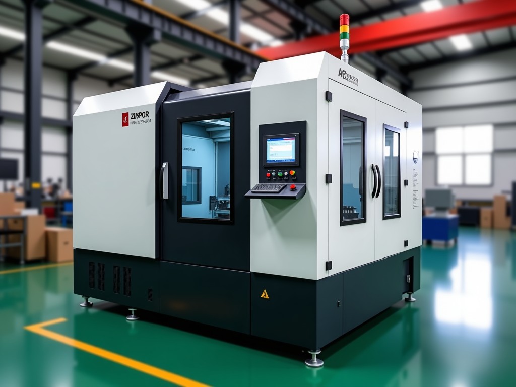
Ce Certified Intelligent High Speed Cold Chamber Die Casting Machine Company
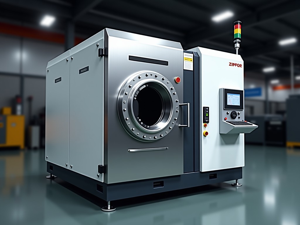
Engineering-driven manufacturer of intelligent high-speed cold chamber die casting systems with full CE certification, serving automotive, electronics, and industrial component OEMs globally. Cold
CE Certified Intelligent High Speed Cold Chamber Die Casting Machine Company
Engineering-driven manufacturer of intelligent high-speed cold chamber die casting systems with full CE certification, serving automotive, electronics, and industrial component OEMs globally.
Technical Foundation of High-Speed Cold Chamber Die Casting
Cold chamber die casting separates the melting furnace from the injection system, allowing processing of high-melting-point alloys such as aluminum, magnesium, and copper-based materials. The molten metal is ladled into a horizontal shot sleeve for each cycle, eliminating continuous contact between the injection mechanism and the melt. This architecture reduces thermal degradation of hydraulic components and extends plunger tip service life by 30–40% compared to hot chamber alternatives.
High-speed variants accelerate the injection phase to 6–12 m/s within 15–30 milliseconds, creating the turbulent flow necessary for thin-wall sections down to 0.8 mm. The intelligent control layer coordinates accumulator pressure, proportional valve response, and real-time position feedback to maintain shot-to-shot velocity variation below ±1.5%. This precision directly reduces porosity in structural components such as EV battery housings and transmission cases.
CE certification confirms compliance with Machinery Directive 2006/42/EC, Low Voltage Directive 2014/35/EU, and EMC Directive 2014/30/EU. For die casting equipment, this translates to mandatory safety functions: two-hand start with anti-tie-down, light curtain protection at the die area, emergency stops at four stations, and guarded shot-end access. Documentation includes risk assessment per EN ISO 12100, electrical schematics per EN 60204-1, and a Declaration of Conformity traceable to the serial number.
Core Technical Specifications
The following table represents typical configuration ranges for our intelligent high-speed cold chamber series. Final values are determined during application engineering based on part geometry, alloy selection, and annual volume targets.
| Parameter | Range / Description | Engineering Note |
|---|---|---|
| Locking Force | 1,600–4,500 kN (160–450 ton) | Four-tie-bar or box-frame; select based on projected area × specific pressure |
| Injection Force (Intensified) | 180–650 kN | Accumulator-assisted; third-phase pressure programmable per cavity |
| Plunger Diameter | 50–110 mm | Match to shot weight; larger diameters reduce velocity for same flow rate |
| Max Injection Velocity | 8–12 m/s (high-speed mode) | Achieved via nitrogen-charged accumulators + servo-proportional valves |
| Shot Position Control | ±0.1 mm repeatability | Magnetostrictive or glass-scale feedback; closed-loop at 1 kHz |
| Die Height (Min–Max) | 350–950 mm | Motorized adjustment with 0.01 mm resolution |
| Tie Bar Clearance (H × V) | 650×650 to 1,150×1,150 mm | Box-frame models offer 15% larger envelope at same tonnage |
| Ejector Force / Stroke | 120–350 kN / 100–250 mm | Hydraulic or servo-electric; programmable multi-stage profiles |
| Control Platform | Beckhoff / Siemens PLC + IPC HMI | OPC UA, MQTT, PROFINET standard; digital twin ready |
| CE Safety Package | Category 3 PL d per EN ISO 13849-1 | Dual-channel safety PLC; validated SISTEMA file supplied |
Intelligent Control Architecture
The term "intelligent" in our context refers to three integrated layers: adaptive shot control, predictive maintenance, and process data infrastructure. The shot control layer executes multi-stage velocity profiles — slow fill, fast fill, intensification — with transition points defined by position rather than time. This eliminates the timing drift inherent in timer-based systems when hydraulic oil viscosity changes across shifts.
Predictive maintenance monitors accumulator pressure decay, proportional valve spool position error, and filter differential pressure. Trend analysis flags degradation 200–500 hours before functional failure. One automotive Tier 1 customer reduced unplanned downtime by 62% after deploying the analytics dashboard across six cells.
Data infrastructure records 50+ parameters per shot at 1 kHz: plunger position, velocity, hydraulic pressure, intensifier pressure, die temperature (8 zones), and cycle timestamps. Data exports via OPC UA to MES or historian systems. Local storage retains 12 months of shot curves for traceability — critical for safety-critical castings requiring PPAP Level 3 submission.
Cold Chamber Process Advantages for High-Melting Alloys
Aluminum alloys (A380, ADC12, AlSi10Mg) solidify at 560–590°C. In hot chamber machines, the gooseneck and plunger remain immersed, causing iron pickup that degrades ductility and increases sludge formation. Cold chamber architecture limits iron contamination to <0.15% over 50,000 shots, verified by spectrographic analysis of returned scrap.
Magnesium alloys (AZ91D, AM60B) require protective cover gas (SF6 or Novec 612) during melting and transfer. Our shot-end design integrates a sealed sleeve with gas purge ports, maintaining <50 ppm oxygen at the melt surface during ladling. This reduces oxide film entrapment — the primary cause of fatigue failure in Mg structural parts.
Copper-based alloys (brass, bronze) operate at 950–1,050°C. The cold chamber sleeve uses H13 tool steel with 0.3 mm nitride case, achieving 8,000–12,000 shots before re-nitriding. Water-cooling channels maintain sleeve ID temperature below 250°C, preventing soldering and extending die life by 2× versus uncooled sleeves.
Application Engineering by Industry
Automotive structural components — shock towers, subframe nodes, battery enclosures — demand consistent density across 3–6 mm sections. The intelligent shot profile applies a tailored velocity curve: 0.3 m/s during runner fill, 8 m/s through gates, 12 m/s for final cavity fill, then 180 MPa intensification held for 80 ms. This sequence minimizes air entrapment while preventing cold shuts in thin ribs.
Electronics housings (5G base station covers, server heat sinks) require EMI shielding integrity and thermal conductivity >150 W/m·K. Porosity below 0.5% volume fraction is non-negotiable. Real-time vacuum monitoring (target <50 mbar before injection) combined with velocity profiling achieves this without post-casting impregnation.
Industrial motor housings and pump bodies prioritize dimensional stability over 10,000-hour thermal cycles. The control system stores die temperature maps linked to each cavity. When the infrared sensor network detects a 5°C deviation, the next shot automatically adjusts spray volume and intensification delay — no operator intervention.
Manufacturing Quality Assurance
Every machine undergoes a 72-hour run-in at the factory before shipment. The protocol includes: 500 dry cycles for hydraulic stability, 200 live shots with A380 alloy for shot-end validation, and 100 cycles at maximum locking force for tie-bar strain verification. Strain gauges on all four tie bars confirm parallelism within 0.02 mm/m — exceeding the EN 16780-1 requirement of 0.05 mm/m.
Geometric accuracy is verified by laser tracker: platen parallelism, tie-bar squareness, and ejector plate flatness. Results are compiled into a Machine Accuracy Certificate shipped with the equipment. Customers may witness the run-in on-site or via live stream with synchronized data overlay.
Electrical panels are built to UL 508A alongside CE requirements, enabling dual-market deployment (EU/NA) without rewiring. Component selection favors Schneider, Siemens, and Phoenix Contact — globally available for spare parts within 48 hours. The safety PLC program is password-protected but source code is provided in escrow for long-term maintainability.
Customization Options
Standard configurations cover 70% of inquiries. The remaining 30% require engineered modifications, which we classify into three tiers:
- Tier 1 — Parameter configuration: Shot profiles, die height limits, ejector sequences, language packs, network addresses. Completed during commissioning at no extra cost.
- Tier 2 — Hardware modules: Vacuum valve integration (up to 4 circuits), automatic ladler interface, robotic extractor mounting pattern, servo-electric ejector upgrade, die cooling manifold with flow monitoring. 4–6 week lead time adder.
- Tier 3 — Structural adaptation: Extended tie-bar spacing for family dies, rotating bolster for multi-cavity indexing, integration with trim press or leak test station in-cell. Requires mechanical design review; 10–14 week lead time adder.
All customizations maintain CE compliance. Modified safety functions are re-validated per EN ISO 13849-1 with updated SISTEMA files. Documentation package expands accordingly — no "undocumented features" that complicate future audits.
Frequently Asked Technical Questions
What information is required for a detailed quotation?
Part drawings (STEP/IGES), annual volume, alloy grade, projected area, wall thickness distribution, surface finish requirements, and any secondary operations (machining, leak test, coating). Cycle time targets and floor space constraints help size the automation interface.
Can the machine be integrated with our existing MES/SCADA system?
Yes. The control platform exposes 200+ OPC UA nodes covering process parameters, alarms, maintenance counters, and quality tags. We provide a companion specification document mapping node IDs to engineering units. Integration typically requires 2–3 days of PLC-side configuration.
How is shot-end wear managed in high-volume production?
The intelligent system tracks cumulative shot count per plunger tip and sleeve. At 80% of rated life (configurable), the HMI generates a predictive alert. Tip replacement takes 15 minutes; sleeve replacement 45 minutes. Both are accessible from the operator side without die removal.
What is the typical production lead time after order confirmation?
Standard configurations: 16–20 weeks. Tier 2 customizations: 20–26 weeks. Tier 3 structural adaptations: 26–34 weeks. A detailed project schedule with milestones (design freeze, FAT, SAT) is issued at order acknowledgment.
How are export shipments protected for sea freight?
Machines are shrink-wrapped with VCI film, desiccant packs calculated per EN 12080, and bolted to fumigated timber skids with ISO corner castings. Hydraulic tank is filled with nitrogen blanket at 0.5 bar. A humidity indicator card is placed inside the wrap for arrival inspection.
Is operator training included?
Three days of on-site training are standard: day one — safety systems and basic operation; day two — shot profile optimization and quality troubleshooting; day three — preventive maintenance and data analytics. Training materials are provided in English, German, Chinese, and Spanish. Refresher courses available annually.
Ready to Discuss Your Die Casting Application?
Our application engineers review part geometry, alloy selection, and volume targets to recommend the optimal machine configuration — including shot-end sizing, automation interface, and CE safety validation. No generic catalog pushing.
Submit Technical Inquiry