B2B Die Casting Automation System Production Line Company
A die‑casting automation line integrates melting, injection, cooling, trimming, and inspection into a single, PLC‑controlled flow. The goal is to reduce manual handling, keep cycle times repeatable,
B2B Die Casting Automation System Production Line
A die‑casting automation line integrates melting, injection, cooling, trimming, and inspection into a single, PLC‑controlled flow. The goal is to reduce manual handling, keep cycle times repeatable, and deliver dimensional stability across high‑volume runs.
System Architecture Overview
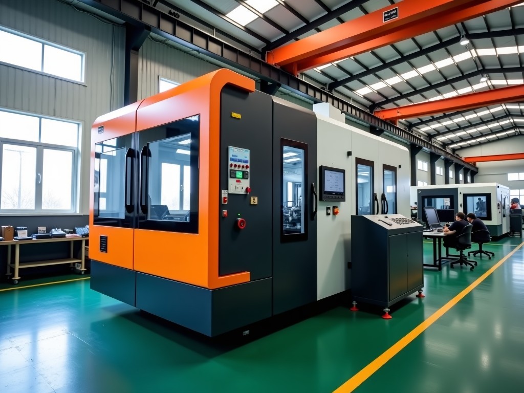
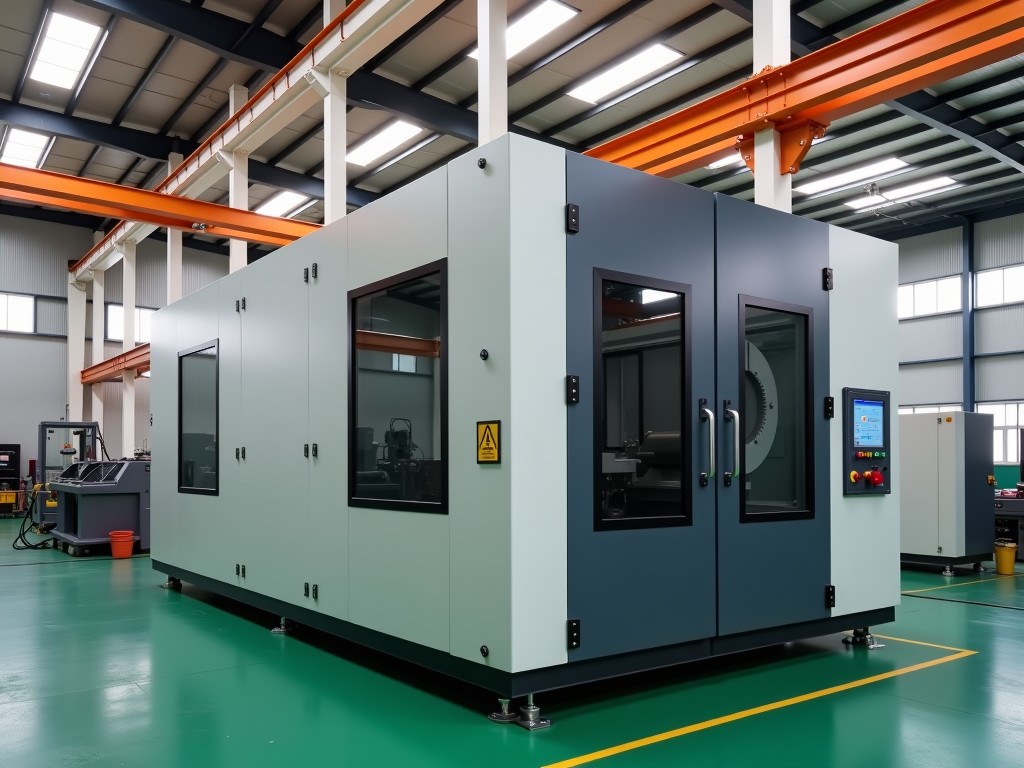
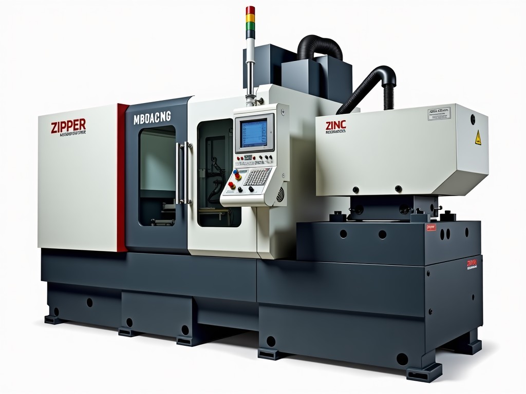
The line starts with a holding furnace that maintains alloy temperature within ±5 °C. A servo‑driven ladle transfers a precise shot weight to the shot sleeve, where a high‑pressure injection unit forces molten metal into a pre‑heated die. After solidification, a robotic extractor moves the casting to a conveyor‑based cooling zone, followed by an automated trimming cell and an inline vision/X‑ray inspection station. All stations communicate over an industrial Ethernet backbone (Profinet or EtherCAT) to a central MES gateway.
Key Components and Their Functions
- Holding furnace – induction or resistance heated, capacity 500 kg–5 t, temperature uniformity ±3 °C.
- Shot sleeve & injection unit – servo‑controlled plunger, pressure up to 1,200 bar, shot weight repeatability ±0.2 %.
- Die set – multi‑cavity, hardened H13 steel, interchangeable inserts for quick changeover.
- Robotic extractor – 6‑axis articulated arm, payload 30–120 kg, cycle‑synchronized with PLC.
- Cooling conveyor – forced‑air or water‑mist zones, adjustable dwell time 5–30 s.
- Trimming cell – CNC‑type rotary trim or laser cut, tool change < 30 s.
- Inspection station – structured‑light 3D scanner + X‑ray for porosity, data logged to SPC database.
Integration, Control, and Data Flow
A safety‑rated PLC (SIL 3) orchestrates motion, temperature, and pressure profiles. The HMI presents real‑time KPI dashboards: cycle time, scrap rate, energy per kilogram. OPC‑UA servers expose process tags to the plant MES, enabling traceability from alloy lot to finished part. Remote diagnostics are supported via a secured VPN tunnel, allowing firmware updates without line stoppage.
Customization Options
Every line is engineered to the customer’s part geometry, annual volume, and floor‑space constraints. Typical decisions include:
- Clamping force: 400 t–4,000 t, matched to projected part size.
- Number of cavities: 1–8, balanced against cycle time targets.
- Alloy family: Al‑Si, Al‑Mg, Zn‑Al, Mg‑Al; furnace power sized accordingly.
- Layout: straight‑line, U‑cell, or modular island for future expansion.
- Automation level: semi‑automated (operator load/unload) to fully lights‑out.
Quality Assurance Philosophy
Process capability is verified during commissioning with a minimum of 30 consecutive shots per cavity. Cp/Cpk targets of ≥1.33 on critical dimensions are documented. In‑line SPC charts trigger automatic alarms when a parameter drifts beyond 1.5 σ. All inspection data are stored for a minimum of 5 years to satisfy automotive APQP/PPAP requirements.
Typical Applications and Why They Fit
Automotive structural brackets benefit from the line’s high repeatability and traceability, meeting IATF 16949 audit trails. Electronic housing producers value the rapid changeover and low porosity achieved by the integrated X‑ray station. Industrial hardware manufacturers appreciate the modular layout that allows adding a secondary trimming cell without line redesign.
Technical Specifications
| Parameter | Typical Range | Customization |
|---|---|---|
| Clamping force | 400 t – 4,000 t | Selectable per project |
| Shot weight | 0.5 kg – 30 kg | Adjusted by sleeve diameter |
| Cycle time (dry) | 12 s – 45 s | Optimised for cavity count |
| Alloy temperature control | ±3 °C | ±1 °C on request |
| Automation level | Semi‑auto to lights‑out | Configurable per station |
| Communication protocol | Profinet / EtherCAT / OPC‑UA | Customer‑specified fieldbus |
Frequently Asked Questions
Can the line dimensions be tailored to an existing building footprint?
Yes. During the concept phase we generate a 3‑D layout that respects column spacing, ceiling height, and utility routing. The modular frame can be shortened or extended in 500 mm increments.
What information is required before a formal quotation?
Part CAD model, annual volume, alloy grade, required Cp/Cpk, available floor area, and preferred automation level. A short process questionnaire accelerates the proposal.
Which alloys can be processed on the same line?
The furnace and shot sleeve are sized for a primary alloy family. Switching between Al‑Si and Zn‑Al is possible with a dedicated change‑over kit (≈4 h). Simultaneous multi‑alloy operation is not supported.
How is quality inspected during production?
Every casting passes a structured‑light scanner for dimensional check and an X‑ray module for internal porosity. Results are compared to the SPC limits in real time; out‑of‑spec parts are automatically diverted to a reject bin.
What is the typical lead time from order to commissioning?
Standard configurations ship in 16–20 weeks; highly customized cells may require 24–30 weeks. A detailed project schedule is provided after the design freeze.
How are spare parts and service managed after start‑up?
A recommended spare‑parts kit (critical seals, sensors, trim tools) is quoted with the line. Remote monitoring contracts include quarterly health reports and 24/7 hotline access.
Next Steps
Share your part specifications and volume targets to receive a preliminary layout and budget estimate. Our engineering team will review the data and propose a configuration that balances cycle time, floor space, and total cost of ownership.