Direct Factory Die Casting Machine Replacement Spare Parts Supplier
Supplying replacement components for high‑pressure die casting equipment requires precise dimensional control, material traceability, and a clear understanding of the thermal‑mechanical cycles each
Direct Factory Die Casting Machine Replacement Spare Parts Supplier
Supplying replacement components for high‑pressure die casting equipment requires precise dimensional control, material traceability, and a clear understanding of the thermal‑mechanical cycles each part endures. This page outlines the product scope, material choices, manufacturing controls, and customization pathways that enable procurement teams to reduce downtime risk and total cost of ownership.
Product Scope
The catalog covers every wear‑exposed assembly on cold‑chamber and hot‑chamber machines from 150 t to 4 000 t clamping force. Typical categories include:
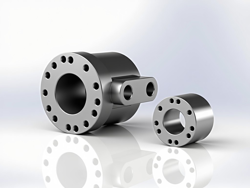
- Shot sleeves and plunger tips (H13, 1.2344, or proprietary alloys)
- Die inserts, core pins, and ejector pins (pre‑hardened 420 SS, 1.2367, or carbide‑tipped)
- Nozzle bodies, sprue bushings, and runner plates (heat‑treated 1.2343)
- Hydraulic cylinder seals, guide bushes, and wear plates (PTFE‑filled bronze, polyurethane)
- Electrical heating elements, thermocouple sheaths, and control‑board connectors
Each item is produced to the original equipment manufacturer’s drawing set or to a customer‑supplied CAD model, ensuring interchangeability without machine re‑qualification.
Material Options
Material selection is driven by operating temperature, abrasive wear, and corrosion exposure. The table below summarizes the most common grades and their typical service windows.
| Component Type | Standard Grade | Optional Up‑grade | Typical Hardness (HRC) |
|---|---|---|---|
| Shot sleeve / plunger tip | H13 (1.2344) | Maraging 300 / Ceramic‑coated | 48‑52 |
| Die insert / core pin | 1.2367 (pre‑hardened) | Carbide‑tipped / PVD‑coated | 50‑55 |
| Nozzle body / sprue bushing | 1.2343 (heat‑treated) | Inconel 718 for high‑temp alloys | 45‑48 |
| Hydraulic seal / guide bush | PTFE‑filled bronze | Polyurethane 95A | N/A |
All grades are sourced with mill certificates; heat‑treatment records are retained for traceability.
Manufacturing & Inspection Controls
Production follows a defined process flow that mirrors OEM qualification steps:
- Raw‑material verification (chemical analysis, ultrasonic testing for bar stock)
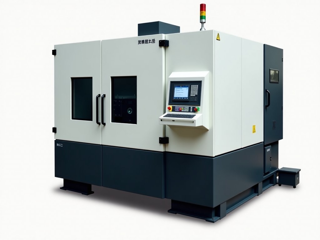
- CNC roughing and finishing on 5‑axis machines with in‑process probing
- Heat‑treatment in vacuum furnaces; hardness mapping on each lot
- Surface treatment (nitriding, PVD, or ceramic coating) per drawing spec
- Final dimensional inspection using CMM (±0.005 mm on critical features) and surface‑roughness profilometry
- Functional pressure‑test on hydraulic components (1.5× rated pressure)
Inspection reports are packaged with each shipment; statistical process control charts are available for long‑term supply agreements.
Customization Capabilities
Beyond standard catalog items, the factory supports:
- Reverse‑engineered parts from worn samples (3‑D scan → CAD → prototype)
- Design‑for‑manufacture feedback to reduce machining steps and material waste
- Batch sizes from single‑piece prototype to 5 000 pcs/year with configurable lead times
- Private‑label packaging and documentation for OEM distributors
Engineering review is performed before quotation; a design‑freeze checklist ensures no hidden changes after tooling release.
Typical Applications & Why They Fit
Automotive structural castings demand shot sleeves that survive 10⁶ cycles at 650 °C; the H13‑nitrided option delivers the required thermal fatigue resistance while maintaining dimensional stability. Consumer‑electronics housings run at lower pressures but higher cycle rates; carbide‑tipped core pins reduce galling on aluminum alloys. Heavy‑industry gear housings use large‑diameter nozzles where Inconel 718 resists erosion from magnesium‑rich melts. In each case the material‑property match is documented in the inspection package, allowing the buyer to justify the selection to quality auditors.
Technical Specifications Summary
| Parameter | Typical Range / Value | Customizable? |
|---|---|---|
| Clamping force coverage | 150 t – 4 000 t | Yes |
| Maximum operating temperature | 700 °C (shot sleeve) | Yes (material upgrade) |
| Dimensional tolerance (critical) | ±0.005 mm | Yes (tighter on request) |
| Surface roughness (Ra) | 0.4 µm – 0.8 µm | Yes |
| Lead time (standard catalog) | 3‑4 weeks | Expedited 10‑12 days |
Frequently Asked Questions
- Can dimensions be customized? Yes. Provide a 3‑D model or 2‑D drawing with tolerances; we return a DFM review within 48 hours.
- What information is required before quotation? Part number or drawing, material grade (or service conditions), annual volume, and desired lead time.
- Which materials are available? Standard grades listed above; additional alloys (e.g., 1.2369, 1.2083, nickel‑based superalloys) on request.
- How is quality inspected? Full CMM inspection, hardness mapping, surface‑roughness measurement, and pressure testing where applicable. Reports ship with each order.
- What packaging methods are offered? Vacuum‑sealed anti‑corrosion bags, wooden crates with foam inserts, or custom crating per customer spec.
- How are export shipments protected? ISPM‑15 compliant pallets, desiccant packs, and shock‑indicator labels for high‑value items.
- What is the typical production lead time? 3‑4 weeks for catalog items; 5‑7 weeks for new tooling or reverse‑engineered parts.
- How are samples arranged? First‑article samples are produced after drawing approval; shipping cost is credited on the first production order.
Ready to discuss your die‑casting spare‑part requirements? Our engineering team can review drawings, suggest material upgrades, and provide a firm quotation within two business days.
Request a Quote