Wholesale Industrial Metal Zipper Production Equipment Factory
This page details the complete range of metal zipper manufacturing machinery available for bulk procurement. The equipment covers every stage from wire feeding and tooth forming to slider attachment
Wholesale Industrial Metal Zipper Production Equipment Factory
This page details the complete range of metal zipper manufacturing machinery available for bulk procurement. The equipment covers every stage from wire feeding and tooth forming to slider attachment and final inspection, allowing a single source to supply an entire production line.
Buyers typically evaluate throughput, tooth profile accuracy, and changeover time when selecting a line. The machines described below are engineered for continuous 24‑hour operation with modular tooling that reduces downtime during product switches.
Core Machine Modules
A standard line consists of four primary modules. Each module can be ordered independently or as a synchronized set with a shared PLC platform.
- Wire Feeding & Straightening Unit – Servo‑driven rollers maintain tension within ±0.02 mm, preventing tooth distortion.
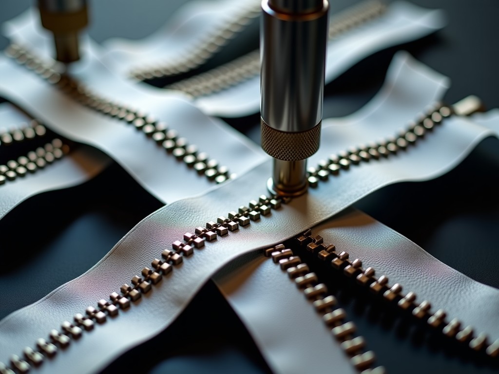
- Tooth Forming Press – Interchangeable dies produce standard Y‑type, European, or custom profiles; cycle time adjustable from 30 ms to 120 ms.
- Slider Assembly Station – Vision‑guided pick‑and‑place aligns sliders to within 0.05 mm; supports metal, plastic, and coated sliders.
- Final Inspection & Packaging Conveyor – Optical sensors verify tooth pitch, slider function, and surface finish; rejects are diverted automatically.
All modules communicate via EtherCAT, enabling real‑time data exchange for OEE monitoring and predictive maintenance.
Typical Technical Specifications
| Parameter | Typical Value | Customizable Range |
|---|---|---|
| Maximum line speed | 120 m/min | 80‑150 m/min |
| Wire diameter | 0.30‑0.60 mm | 0.20‑0.80 mm |
| Tooth pitch accuracy | ±0.015 mm | ±0.010 mm (high‑precision dies) |
| Installed power | 45 kW | 30‑70 kW |
| Overall footprint (L×W×H) | 12 m × 3 m × 2.5 m | Modular, per layout |
| Weight (complete line) | ≈ 18 t | Depends on module count |
Values shown represent the most common configuration for 5‑mm metal zippers. Exact figures are confirmed during the quotation phase based on the customer’s zipper profile, material, and required output.
Why This Line Fits Heavy‑Duty Applications
Industrial sectors such as automotive seating, heavy‑duty luggage, and protective gear demand zippers that withstand high tensile loads and repeated cycling. The tooth forming press uses hardened tool steel (HRC 58‑62) and a closed‑loop force controller that maintains forming pressure within 1 % of setpoint, eliminating the tooth‑cracking risk seen on lower‑cost machines.
The slider station’s vision system inspects each slider for correct orientation and surface defects before insertion, a critical step when the final product must meet ISO 15199 durability standards. Because the inspection data is logged per unit, traceability reports can be generated automatically for quality audits.
Customization Options
Every line can be tailored to the buyer’s product portfolio. The most requested adjustments are listed below; additional modifications are evaluated on a project basis.
- Die sets for non‑standard tooth shapes (e.g., double‑lock, waterproof profiles).
- Extended wire feeder for coil diameters up to 1 m.
- Integration of laser marking for batch codes on the zipper tape.
- Alternative PLC brands (Siemens, Allen‑Bradley, Mitsubishi) to match plant standards.
- Clean‑room compatible enclosures with HEPA filtration for medical‑grade zipper production.
A configuration worksheet is provided after the initial inquiry; completing it enables a detailed layout drawing and a firm price within five business days.
Quality Assurance & Acceptance Testing
Each machine undergoes a three‑stage test before shipment:
- Factory Acceptance Test (FAT) – 8‑hour run at rated speed with the customer’s wire sample; data recorded for tooth pitch, slider pull force, and cycle consistency.
- Vibration and thermal stability check – sensors verify that bearing temperatures stay below 70 °C under continuous load.
- Documentation package – includes CE declaration, electrical schematics, maintenance manuals, and a spare‑parts list with recommended stocking quantities.
Customers are welcome to witness the FAT on‑site or via live video link; a recorded session is supplied when travel is not feasible.
Packaging, Shipping & Installation Support
Modules are shipped on custom steel skids with vibration‑damping pads. Each skid is sealed in a vapor‑corrosion‑inhibitor (VCI) film and marked with handling orientation arrows. Standard export packaging complies with ISPM‑15 for wooden components.
On‑site commissioning includes:
- Mechanical alignment and leveling to ±0.1 mm/m.
- Electrical hookup verification and PLC program upload.
- Operator training (2 days) covering changeover, routine maintenance, and fault diagnostics.
Remote diagnostics are available for the first 12 months through a secure VPN tunnel, reducing travel costs for minor adjustments.
Frequently Asked Questions
- Can the line produce both 5 mm and 8 mm metal zippers?
- Yes. The tooth forming press accepts interchangeable die sets; changeover takes roughly 45 minutes with the quick‑release tooling system.
- What information is needed for a formal quotation?
- Required zipper profile drawings, wire material grade, target daily output, preferred PLC brand, and any clean‑room or certification requirements.
- Are spare parts stocked locally?
- Critical wear items (dies, rollers, sensors) are kept in regional warehouses in Europe, North America, and Southeast Asia; lead time for non‑stock items is typically 4‑6 weeks.
- How is the equipment protected against power fluctuations?
- Each module includes an integrated line reactor and a UPS‑rated power supply for the PLC and vision system, maintaining operation during brief dips up to 200 ms.
- What is the typical production lead time after order confirmation?
- Standard configurations ship in 10‑12 weeks; customized lines require 14‑18 weeks depending on die development.
Next Steps
To receive a detailed layout, pricing, and a proposed delivery schedule, please submit your project specifications. Our engineering team will review the data and respond with a tailored proposal within five business days.
For immediate technical questions, call the direct line listed on the contact page.