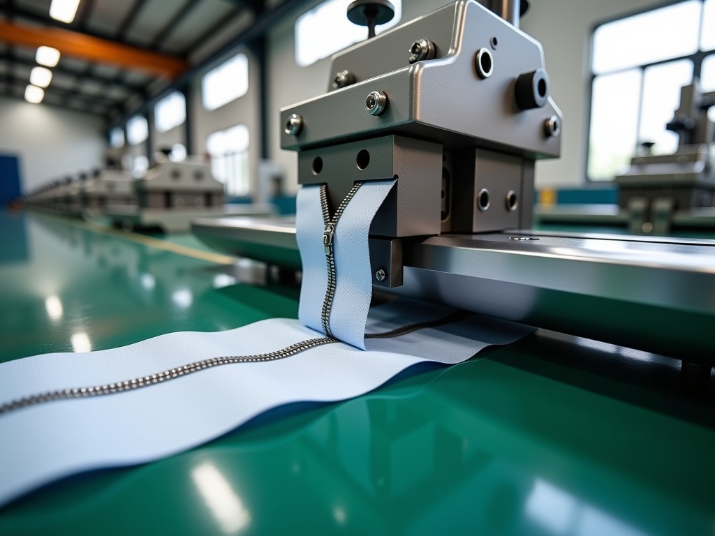
Custom Zipper Punching Machine Manufacturer
Engineered for high-volume zipper tape perforation, our custom punching systems integrate servo-driven indexing, modular die stations, and real-time tension control to match specific tooth profiles,
Custom Zipper Punching Machine Manufacturer
Engineered for high-volume zipper tape perforation, our custom punching systems integrate servo-driven indexing, modular die stations, and real-time tension control to match specific tooth profiles, tape widths, and production throughput targets.
Core Engineering Principles
Standard off-the-shelf punching units often force compromises on pitch accuracy or tape handling stability. A custom-built machine starts with the zipper specification — tooth geometry, tape material (polyester, cotton, aramid), and required pitch tolerance — then reverse-engineers the drive train, die clearance, and clamping force profile. This approach eliminates the trial-and-error phase common when retrofitting generic equipment.
Servo synchronization between the feed rollers and the punching ram is the critical variable. Mechanical cam-driven systems accumulate timing drift at speeds above 120 strokes per minute. Our architecture replaces cams with electronically geared servo axes, maintaining ±0.02 mm positional registration even during acceleration and deceleration ramps. The result is consistent tooth engagement force across the full coil length.
Technical Configuration Overview
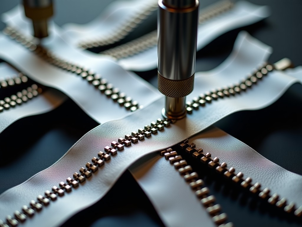
Every project begins with a finite element analysis (FEA) of the die set under peak load. This simulation validates punch penetration depth, stripper plate deflection, and heat buildup in the tool steel. The data informs the selection of die material — typically AISI D2 for standard nylon coils, or CPM 10V powder metallurgy for abrasive aramid tapes — and determines the required press frame rigidity to prevent angular misalignment.
| Parameter | Typical Range / Option | Customization Logic |
|---|---|---|
| Punching Stroke Rate | 80 – 200 SPM | Matched to tape tensile strength and die cooling capacity |
| Tape Width Capacity | 8 mm – 45 mm | Guide rail spacing and clamp jaw profile machined per order |
| Pitch Accuracy (CPK) | ≥ 1.33 @ ±0.03 mm | Closed-loop encoder feedback on feed axis |
| Die Station Count | Single, Dual, or Quad-row | Determined by annual volume and changeover frequency |
| Drive System | AC Servo (Feed + Ram) | Electronic gearing replaces mechanical timing gears |
| Control Platform | Siemens S7-1500 / Beckhoff CX | OPC UA ready for MES integration |
Die Technology and Tooling Strategy
The die set defines the cost per million punches. We supply quick-change cassettes with pneumatic locking, reducing setup from 45 minutes to under 8 minutes. Each cassette carries its own RFID tag storing sharpening history, cumulative stroke count, and material batch ID. The controller reads this data at startup and adjusts ram dwell time automatically to compensate for progressive edge wear.
For coated tapes (PU, TPU, silicone), standard punching generates adhesive buildup on the punch face. Our solution integrates a micro-mist lubrication system — food-grade, non-staining — delivered through internal channels in the punch tip. Flow rate is pulse-width modulated per stroke, eliminating overspray onto the tape surface. This feature alone extends die life by 30–40% in coated applications.
Tape Handling and Tension Architecture
Inconsistent tension is the primary cause of pitch error. The feed module uses dual-motor differential drive: a master servo on the pull roller and a slave torque motor on the unwind stand. A laser micrometer measures tape width in real time; the controller adjusts nip pressure to prevent edge waving without marking delicate surfaces. For ultra-lightweight tapes (< 15 g/m²), an optional vacuum-assisted guide plate stabilizes the web through the die zone.
- Active dancer arm with load cell feedback — tension range 0.5–15 N, resolution 0.02 N
- Automatic splice detection via optical contrast sensor — triggers controlled deceleration
- Static elimination bars at entry and exit — critical for synthetic tapes in low-humidity environments
Integration and Data Exchange
Modern zipper lines require traceability. The machine publishes a structured data stream — stroke count, force profile per punch, tension trend, die ID, timestamp — via MQTT or OPC UA. Quality engineers can correlate a specific coil batch with the exact force signature of each tooth. This capability supports root-cause analysis when downstream assembly reports engagement failures.
Remote diagnostics are standard. The HMI runs a hardened Linux image with VPN access for firmware updates, parameter backup, and real-time oscilloscope views of servo current loops. No proprietary software licenses are required on the customer side; a standard browser accesses the full dashboard.
Application-Specific Engineering
Automotive airbag zippers demand zero-burr punching on aramid tape. We validate each die set with a 10,000-stroke pre-run, measuring burr height via confocal microscopy. Medical garment zippers require biocompatible lubricants and cleanroom-compatible frame finishes (electropolished 316L stainless). Outdoor gear manufacturers often need variable pitch patterns — alternating long/short teeth for snow-proof sealing — which the servo ram profiles handle without mechanical cam changes.
Quality Verification Protocol
Before shipment, every machine completes a 4-hour Site Acceptance Test (SAT) protocol at our facility using the customer's actual tape material. The test records:
- Pitch distribution histogram across 50,000 consecutive teeth
- Punch force waveform repeatability (CPK ≥ 1.67)
- Thermal stability of die temperature over 3 hours continuous operation
- Tension ripple spectrum at maximum line speed
Customers receive the raw dataset, not just a pass/fail certificate. This transparency allows their process engineers to set realistic SPC limits for incoming inspection.
Lead Time and Project Flow
Typical engineering-to-delivery cycle spans 14–20 weeks depending on die complexity and control system customization. The critical path usually runs through die manufacturing (6–8 weeks for multi-cavity hardened tooling). We mitigate schedule risk by starting long-lead procurement — servo motors, linear guides, safety-rated PLC — upon receipt of technical specification sign-off, before the commercial contract is finalized.
Frequently Asked Technical Questions
Can the machine handle both nylon and metal coil zippers on the same line?
Yes. The die cassette swap accommodates different punch geometries and clearance values. The controller stores separate recipe files for each material, adjusting ram dwell, feed acceleration, and lubrication pulse width automatically. Changeover typically takes 10 minutes including tension recalibration.
What information is required for a detailed quotation?
We need: zipper type (coil, molded, invisible), tape material datasheet, tooth pitch and profile drawing, target output (meters/day), coil length per batch, and available floor footprint. A 1-meter tape sample allows us to run a trial punch on our test bench and provide measured burr and pitch data with the quote.
How is export packaging handled for oversized frames?
Frames exceeding container height are split at machined flanges with dowel alignment. All machined surfaces receive VCI (volatile corrosion inhibitor) coating and vacuum-sealed barrier bags. Electrical cabinets are desiccant-packed with humidity indicators. We provide 3D container loading plans and on-site reassembly supervision if required.
What spare parts package do you recommend for the first two years?
A standard critical spares kit includes: one complete die cassette per profile, feed roller set (urethane and steel), stripper plate springs, punch guide bushings, and a servo motor brake assembly. We customize the list based on your planned annual volume and maintenance crew skill level. Consumable usage forecasts are included in the SAT report.
Request a Technical Consultation
Share your zipper specifications and production targets. We will return a preliminary layout, cycle time simulation, and tooling strategy within 3 business days.
Submit Project Details