Custom Smart Metal Zipper Manufacturing System Suppliers
A smart metal zipper manufacturing system integrates precision metal forming, electronic component embedding, and automated quality verification into a continuous production line. Unlike conventional
Custom Smart Metal Zipper Manufacturing System Suppliers
A smart metal zipper manufacturing system integrates precision metal forming, electronic component embedding, and automated quality verification into a continuous production line. Unlike conventional zipper machines that only form teeth and assemble tapes, these systems handle microelectronics — RFID chips, temperature sensors, or conductive traces — during the tooth-molding or tape-lamination stages. The result is a zipper that functions as both a mechanical fastener and a data carrier, suitable for supply-chain tracking, anti-counterfeiting, or environmental monitoring.
Suppliers of such systems typically deliver turnkey lines rather than standalone machines. A complete line includes wire drawing and plating for tooth material, progressive stamping or die-casting for tooth forming, pick-and-place modules for chip insertion, ultrasonic or thermal bonding for encapsulation, and inline optical/electrical testing. The control architecture usually relies on a PLC backbone with motion controllers synchronized to ±0.02 mm positional accuracy, ensuring chip alignment within the tooth cavity across production speeds of 60–120 meters per minute.
Typical System Configuration Parameters
| Parameter | Typical Range | Customization Notes |
|---|---|---|
| Tooth pitch | 3.0–8.5 mm (size #3 to #10) | Die set changeover < 45 min |
| Tooth material | Brass, aluminum, stainless steel, zinc alloy | Plating: nickel, antique brass, gunmetal, custom PVD |
| Chip package format | DFN 2×2 mm, WLCSP, bare die, flex-PCB | Feeder adaptation per package outline |
| Embedding method | Over-molding, ultrasonic staking, laser welding | Selected based on chip thermal budget |
| Inline test coverage | RFID read/write, resistance, continuity, vision | Test recipes stored per SKU |
| Production speed | 60–120 m/min (zipper chain) | Speed/quality trade-off configurable |
| Control platform | Siemens S7-1500 / Beckhoff CX / Allen-Bradley ControlLogix | OPC-UA, MQTT, Profinet standard |
| Footprint (L×W×H) | 12–22 m × 3–4 m × 2.5 m | Modular layout for factory integration |
Core Subsystems and Engineering Considerations
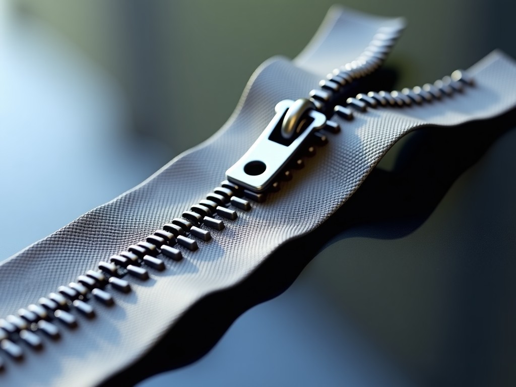
The tooth-forming module determines the mechanical profile and dimensional stability of the zipper. Progressive stamping suits brass and aluminum teeth at high volumes; die-casting is preferred for zinc alloy when complex geometries or thicker cross-sections are needed. In either case, the tooling must maintain tooth-height tolerance within ±0.03 mm to ensure smooth slider engagement after the electronics are embedded. Suppliers with in-house tool rooms can iterate die designs in days rather than weeks, which matters when validating a new chip package.
Chip handling is the differentiating subsystem. A typical pick-and-place head uses vacuum nozzles with 50–100 µm tip diameter, guided by a vision system that locates fiducials on the lead frame or tape pocket. Placement force is monitored in real time — typically 0.3–0.8 N — to avoid die cracking. For bare-die applications, the system adds a flip-chip bonder with thermocompression or ultrasonic bonding, followed by underfill dispensing. The encapsulation station then over-molds the cavity with a thermoplastic (PA66, PBT, or TPU) that must flow around the chip without voids and withstand 150 °C reflow if the zipper later enters a garment assembly line.
Inline testing closes the loop. An RFID reader antenna integrated into the production line verifies each tag's EPC memory and lock status at line speed. For sensor-enabled zippers, a stimulus station applies a known temperature or pressure pulse and reads the digital response. Vision cameras inspect tooth geometry, chip orientation, and encapsulation integrity simultaneously. Defective units are diverted via a high-speed pneumatic gate; yield data feeds back to the MES for SPC trending.
Customization Logic: From Concept to Qualified Line
Customization starts with the zipper specification document: tooth size, tape material (polyester, cotton, aramid), chip part number, and required read range or sensor accuracy. The supplier's application engineers then simulate the thermal profile of the encapsulation step against the chip's maximum reflow temperature — often the limiting factor. If the chip cannot survive 220 °C for 10 seconds, the process shifts to low-temperature ultrasonic staking or UV-cure adhesive, which adds cycle time but preserves functionality.
Tape integration is another customization axis. Some customers need the smart module only on every nth zipper (e.g., one tagged zipper per garment batch). The control system accommodates this through a programmable skip pattern, reducing chip consumption without mechanical changeover. Others require dual-frequency tags (LF + UHF) for both near-field authentication and long-range inventory; the antenna design then becomes a co-engineering effort between the zipper supplier and the tag vendor.
Mechanical validation follows electrical validation. Finished zipper chains undergo cyclic flex testing (typically 5,000–20,000 cycles per ASTM D2061) while monitoring tag readability. Pull-force testing per ASTM D2062 ensures the embedded module does not create a stress concentrator that reduces chain strength below the specified minimum (usually 60–120 N depending on size). Environmental chambers simulate laundry cycles: 75 °C wash, 120 °C tumble dry, repeated 50×, with read-rate logging after each cycle.
Application-Specific Engineering Rationale
In apparel brand protection, the zipper serves as a tamper-evident, serialized identifier. The manufacturing system must guarantee 100% tag commissioning — each EPC written and locked — with a duplicate-detection rate below 1 ppm. This demands a closed-loop verification station that cross-references the written EPC against a cloud database before the zipper leaves the line. The supplier's MES integration capability (REST API, OPC-UA) becomes a selection criterion.
For cold-chain logistics, zippers embed temperature loggers with ±0.5 °C accuracy from -30 °C to +60 °C. The chip's battery (typically a thin-film Li-ion) must survive the encapsulation pressure and temperature. The system therefore includes a pre-encapsulation electrical sort that bins chips by self-discharge rate, placing only the tightest distribution into production. This binning step adds a feeder module but prevents field failures that would compromise shipment integrity data.
Military and tactical gear use conductive-thread zippers that double as antenna structures for body-worn networks. Here the manufacturing system must control the resistivity of the conductive coating on the teeth (target: <5 Ω/cm) while maintaining corrosion resistance per MIL-STD-810. The plating line integrates inline four-point probe measurement, with real-time current-density adjustment. Suppliers with electroplating process control experience reduce the risk of batch rejection at incoming inspection.
Quality Assurance and Acceptance Protocol
Before shipment, a qualified line undergoes a factory acceptance test (FAT) defined by a mutually agreed protocol. The FAT typically runs three consecutive 8-hour shifts at rated speed, tracking: overall equipment effectiveness (OEE) target ≥85%, first-pass yield ≥99.2%, tag read-rate ≥99.9%, and zero critical defects (missing chip, shorted antenna, tooth deformation >0.05 mm). Statistical process control charts for tooth height, chip placement X/Y, and encapsulation wall thickness are reviewed with the buyer's quality team.
Site acceptance test (SAT) repeats key FAT metrics after installation, adding utility consumption verification (compressed air at 0.6 MPa, 1.2 m³/min; electrical 380 V/50 Hz, 45 kVA typical; chilled water 15 L/min at 12 °C). The supplier provides a spare-parts kit calibrated to the buyer's recommended two-year operational profile: die inserts, nozzles, vision lenses, RFID antennas, and critical PLC I/O cards. Documentation includes electrical schematics (EPLAN format), PLC source code (structured text), and 3D models (STEP) for maintenance planning.
Frequently Asked Technical Questions
What information is required before a formal quotation?
Zipper size and tooth profile drawings, tape material and width, chip part number and package datasheet, target production volume (annual meters), required read range or sensor spec, factory utility availability, and desired automation level (fully automatic vs. semi-auto with manual chip loading).
Can the system handle multiple chip packages on the same line?
Yes, through quick-change feeder cassettes and recipe-driven vision alignment. Changeover typically takes 15–25 minutes. The control system stores placement coordinates, bond parameters, and test limits per SKU. However, mixing packages with vastly different thermal budgets (e.g., bare die vs. over-molded DFN) may require separate encapsulation modules.
What is the typical lead time for a custom line?
18–28 weeks from purchase order to FAT, depending on tooling complexity and chip qualification status. Long-lead items are progressive dies (10–14 weeks) and custom vision lighting (6–8 weeks). Parallel engineering — starting die design while chip qualification runs — can compress the schedule by 3–4 weeks.
How is intellectual property protected during co-development?
Standard practice: mutual NDA before technical exchange, followed by a development agreement that defines background IP ownership, foreground IP allocation, and field-of-use restrictions. The supplier typically retains rights to the manufacturing process know-how; the buyer retains rights to the zipper product design and chip application firmware.
What post-installation support is included?
12-month warranty covering parts and remote diagnostics. On-site service visits (typically 2–3 days per quarter for preventive maintenance) are available under a separate service-level agreement. Software updates for PLC and vision algorithms are provided for the platform's commercial life (minimum 7 years). Spare-parts pricing is locked for the first 3 years.
Ready to discuss your smart zipper manufacturing requirements?
Provide your zipper specification, chip datasheet, and target volume. Our application engineers will return a preliminary line concept, budgetary indication, and timeline within 10 business days.
Request Technical Consultation