Custom Open End Zipper Pin Box Machine Manufacturer
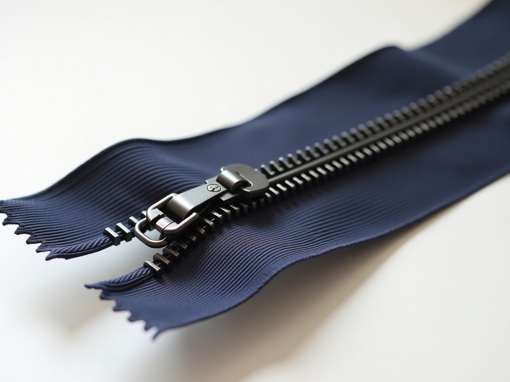
Producing open-end zippers at volume requires precise alignment between the pin, the box, and the tape substrate. A custom pin box machine automates the simultaneous attachment of these two critical
Custom Open End Zipper Pin Box Machine Manufacturer
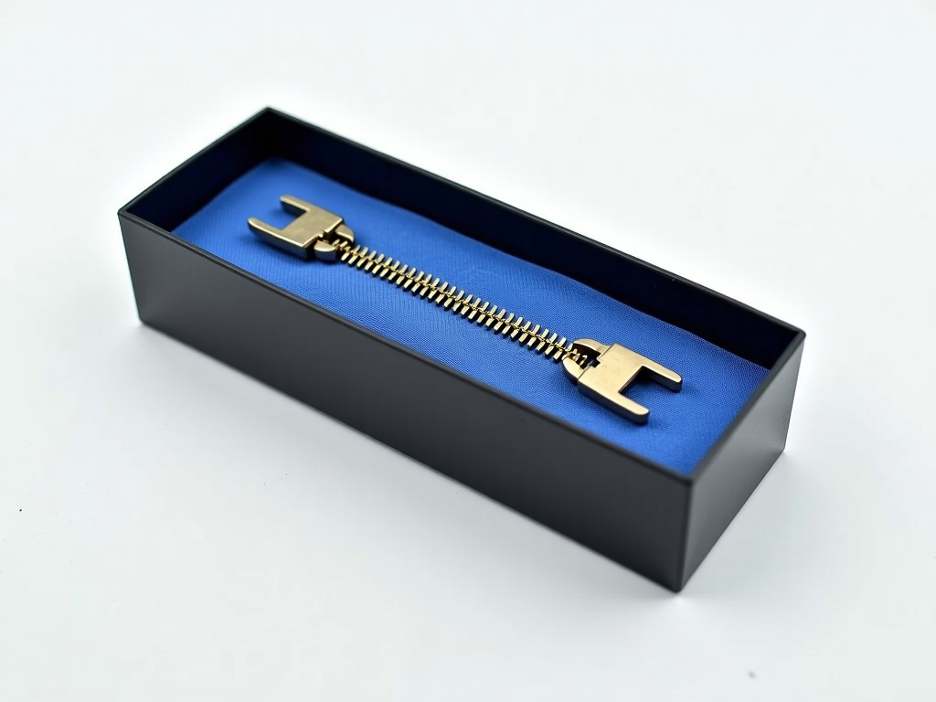
Producing open-end zippers at volume requires precise alignment between the pin, the box, and the tape substrate. A custom pin box machine automates the simultaneous attachment of these two critical components, replacing manual or semi-automatic workflows that introduce misalignment rates exceeding acceptable thresholds for automated garment assembly lines.
Unlike standard chain machines that focus on continuous tooth extrusion, pin box equipment handles discrete component placement. The engineering challenge lies in synchronizing the feeder timing for metal or molded plastic pins with the box insertion mechanism while maintaining tape tension consistency across varying substrate thicknesses, typically ranging from 0.3 mm to 0.8 mm woven polyester or cotton blends.
Customization enters when standard machine frames cannot accommodate non-standard pin geometries, ultra-lightweight tapes requiring vacuum-assisted feeding, or integration requirements into existing zipper chain assembly cells. We design the mechanical architecture around your specific component drawings and target cycle time.
Core Technical Specifications
| Parameter | Standard Range / Capability | Customization Notes |
|---|---|---|
| Compatible Pin/Box Types | Metal (Brass/Aluminum), Molded Plastic, Injection Molded Nylon | Custom vibratory bowl or linear feeder tooling per geometry |
| Tape Width Range | 10 mm – 35 mm (Standard #3, #5, #8, #10) | Adjustable guide rails; special widths up to 50 mm available |
| Production Speed | 60 – 120 pcs/min (dependent on component complexity) | Multi-head configurations for >200 pcs/min |
| Placement Accuracy | ±0.05 mm (Pin-to-Box center alignment) | Vision inspection integration for ±0.02 mm critical apps |
| Drive System | Servo-driven indexing + Cam mechanisms for high-force insertion | Full servo synchronization for quick changeover |
| Control Platform | PLC (Mitsubishi/Siemens) + HMI; Ethernet/IP, Profinet ready | OPC UA / MES data logging for Industry 4.0 compliance |
| Power Requirement | 3-phase 380V/415V 50/60Hz, 5–15 kW | Configurable for regional voltage standards |
| Compressed Air | 0.5 – 0.6 MPa, ~200 NL/min | Air-saving circuits available for high-cycle lines |
Mechanical Architecture & Engineering Approach
The machine frame utilizes a stress-relieved welded steel base (typically Q345B) machined to flatness tolerances of 0.02 mm/m after annealing. This rigidity prevents harmonic vibration during the high-deceleration indexing phases required for precise pin seating. Linear guide rails (THK or HIWIN equivalent, Class H) carry the tape transport carriage, eliminating play that would otherwise accumulate as lateral pin offset.
Feeding systems are engineered per component physics. Metal pins use centrifugal feeders with air-jet orientation to achieve 100% head-up presentation. Molded plastic boxes, prone to static cling and nesting, employ vibratory bowls with coated tracks and ionizing bars. Changeover between pin sizes typically requires 15–20 minutes using quick-release tooling plates pinned to the feeder base.
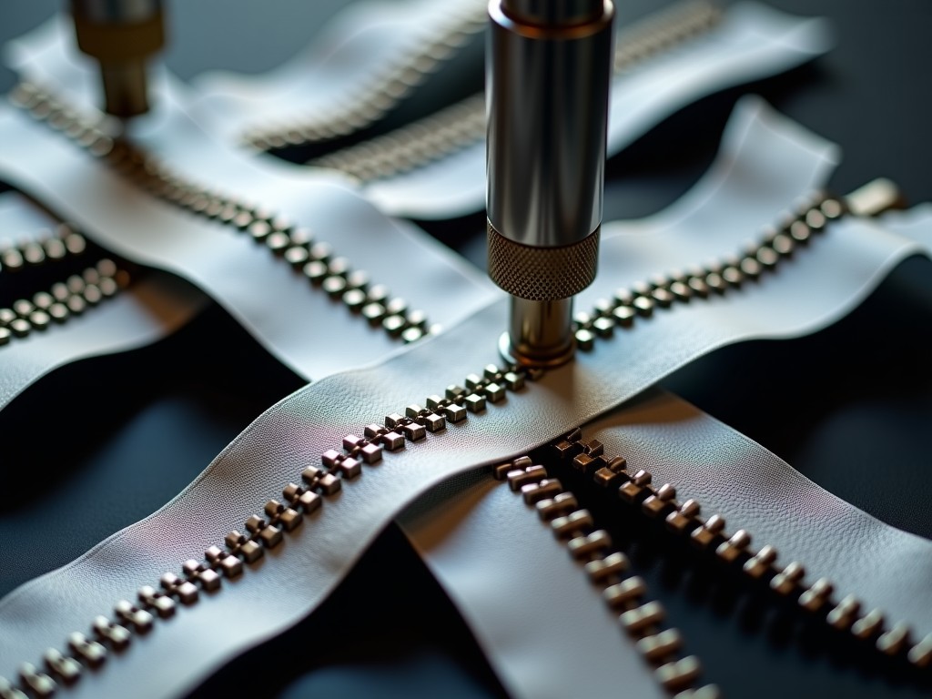
The insertion station employs a dual-stage press: a low-force alignment probe engages the box cavity first, verifying presence and orientation via proximity sensor, followed by the main servo-driven ram applying calibrated force (adjustable 50–500 N) to clinch the pin legs or snap the box locking arms. Force-displacement curves are logged per cycle for statistical process control.
Why Customization Matters for Open-End Zipper Lines
Standard catalog machines assume industry-norm pin geometries (YKK/IDE/OPTILON compatible profiles). However, brands increasingly specify proprietary pin profiles for brand protection or functional differentiation — such as reinforced boxes for heavy-duty outerwear or low-profile pins for seamless knit integration. A custom machine accommodates these geometries without compromising cycle time.
Tape handling is the second major customization driver. Recycled polyester tapes exhibit higher friction variance than virgin material; tension control requires closed-loop dancer arms with load cells rather than simple pneumatic brakes. For waterproof tape with TPU coating, the feed rollers need knurled profiles and heating elements to prevent delamination at the pinch point.
Integration topology varies: some lines require the pin box machine to sit inline between the chain machine and the top-stop/bottom-stop station, demanding matched passline height and synchronized speed following. Others operate as standalone cells feeding a buffer conveyor. We define the mechanical and electrical interface (I/O handshakes, safety circuit categories) during the specification phase.
Available Customization Modules
- Feeder Tooling: Dedicated bowls/tracks per pin/box SKU; quick-change cartridge design for multi-SKU production.
- Vision Verification: Keyence/Cognex integration for pin orientation, box cavity clearance, and post-insertion clinch quality; reject gate actuation < 50 ms.
- Tape Tension Control: Pneumatic dancer, servo-driven nip rolls, or magnetic particle brake options depending on tape elasticity.
- Marking/Printing: Inline laser or hot-stamp marking on tape immediately after pin/box attachment for traceability.
- Data Connectivity: SQL database logging of cycle parameters, force curves, and reject reasons; MES API implementation.
- Safety Standards: Category 3 PL d (ISO 13849) standard; Category 4 PL e with light curtains and safety PLC available.
Application Context by Industry Segment
Apparel & Fast Fashion: High SKU turnover demands rapid changeover. Multi-head servo-synchronized machines with recipe-driven HMI reduce setup from hours to minutes, critical for lot sizes under 5,000 units. Vision inspection prevents mis-clinched pins that cause zipper failure during garment QC.
Outdoor & Technical Gear: Waterproof zippers use coated tapes and oversized pins for pull-strength retention. Machines here require heated feed rollers and higher insertion force capacity (up to 800 N). The box geometry often includes a sealing flange; alignment tolerance tightens to ±0.03 mm to maintain hydrostatic head rating.
Automotive & Industrial Textiles: Seat covers and protective enclosures use heavy-gauge metal zippers (#10, #15). Pin material may be stainless steel requiring hardened feeder tooling and insertion rams. Cycle time is secondary to clamping force repeatability and traceability logging for PPAP documentation.
Quality Assurance & Acceptance Protocol
Every machine undergoes a 72-hour run-off at our facility using your supplied components (or approved equivalents) before shipment. Acceptance criteria include: consecutive 10,000 cycles without jam, placement accuracy Cpk ≥ 1.33, insertion force standard deviation < 3% of mean, and zero false-rejects on vision system over 5,000 good parts.
We provide a complete documentation package: mechanical assembly drawings (PDF + STEP), electrical schematics (EPLAN), PLC/HMI source code (unlocked), safety validation report, and a recommended spare parts list categorized by wear rate (A: monthly, B: quarterly, C: annual). Remote VPN access to the PLC is standard for post-installation diagnostics.
On-site commissioning typically requires 3–5 days including operator training, recipe optimization for your tape batches, and MES handshake validation. First-article inspection reports (FAIR) per AS9102 or your internal format are generated during this phase.
Frequently Asked Technical Questions
What component data is required for quotation?
We need 2D/3D drawings of the pin and box (STEP or IGES preferred), material specification, tape width/construction/thickness, target daily volume, and available floor footprint. Photos of existing components with caliper measurements suffice for preliminary layout.
Can one machine handle multiple pin/box sizes?
Yes, within a defined platform range (e.g., #3 to #8). Changeover involves swapping feeder tooling cartridges, tape guide rails, and insertion nests — typically 20 minutes. For wider ranges (#3 to #15), a dual-platform or modular frame is recommended to maintain rigidity.
How is insertion force monitored and controlled?
The servo ram records force vs. position at 1 kHz sampling. Upper/lower limits are set per recipe. Cycles exceeding limits trigger immediate reject and data logging. This replaces destructive pull-test sampling with 100% in-process verification.
What is the typical lead time for a custom build?
12–16 weeks from design freeze to factory acceptance test (FAT), depending on feeder complexity and vision integration. Standard platform machines with custom tooling only: 8–10 weeks. Expedited schedules are possible with parallel engineering workflows.
How are spare parts and long-term support handled?
We maintain a 10-year parts availability commitment. Critical wear items (feeder tracks, insertion punches, guide rails) are manufactured in-house or sourced from defined OEM partners with controlled drawings. Preventive maintenance schedules and video-based training modules are included in the handover package.
Ready to Define Your Pin Box Automation Project?
Share your component drawings, volume targets, and line integration requirements. We will return a preliminary layout concept, cycle time analysis, and budgetary quotation within 5 business days.
Submit Technical Inquiry