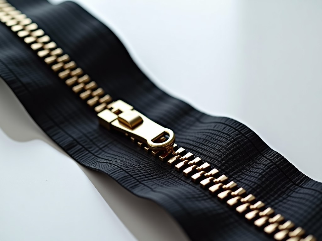
Custom Metal Zipper Machinery Top Factory
Modular forming, punching, and assembly systems built to your tooth profile, tape width, and throughput requirements — delivered with documented process validation. Standard off-the-shelf zipper
Custom Metal Zipper Machinery — Engineered for Precision Chain Production
Modular forming, punching, and assembly systems built to your tooth profile, tape width, and throughput requirements — delivered with documented process validation.
Why Metal Zipper Machinery Requires Custom Engineering
Standard off-the-shelf zipper machines rarely match the tooth geometry, tape material, or cycle-time targets of a specific product line. A brass jean zipper with 4.5 mm pitch behaves differently under forming dies than a nickel-silver outdoor zipper at 6.0 mm pitch — the spring-back, work-hardening rate, and lubrication demand all shift.
We design each line around your approved tooth profile drawing and tape specification. The forming module, punch progression, and clinching station are machined as matched sets, not interchangeable generics. This reduces setup scrap from 12–18 % down to 3–5 % in typical first-article runs.
When volume scales, the same platform accepts additional lanes or a higher-speed cam indexer without replacing the base frame — capital expenditure stays aligned with demand curves.
Core Machine Modules & Configuration Logic
A complete metal zipper line typically combines five synchronized modules. Each module is selectable independently, allowing you to invest only in the process steps you need in-house.
| Module | Primary Function | Customization Levers | Typical Cycle Range |
|---|---|---|---|
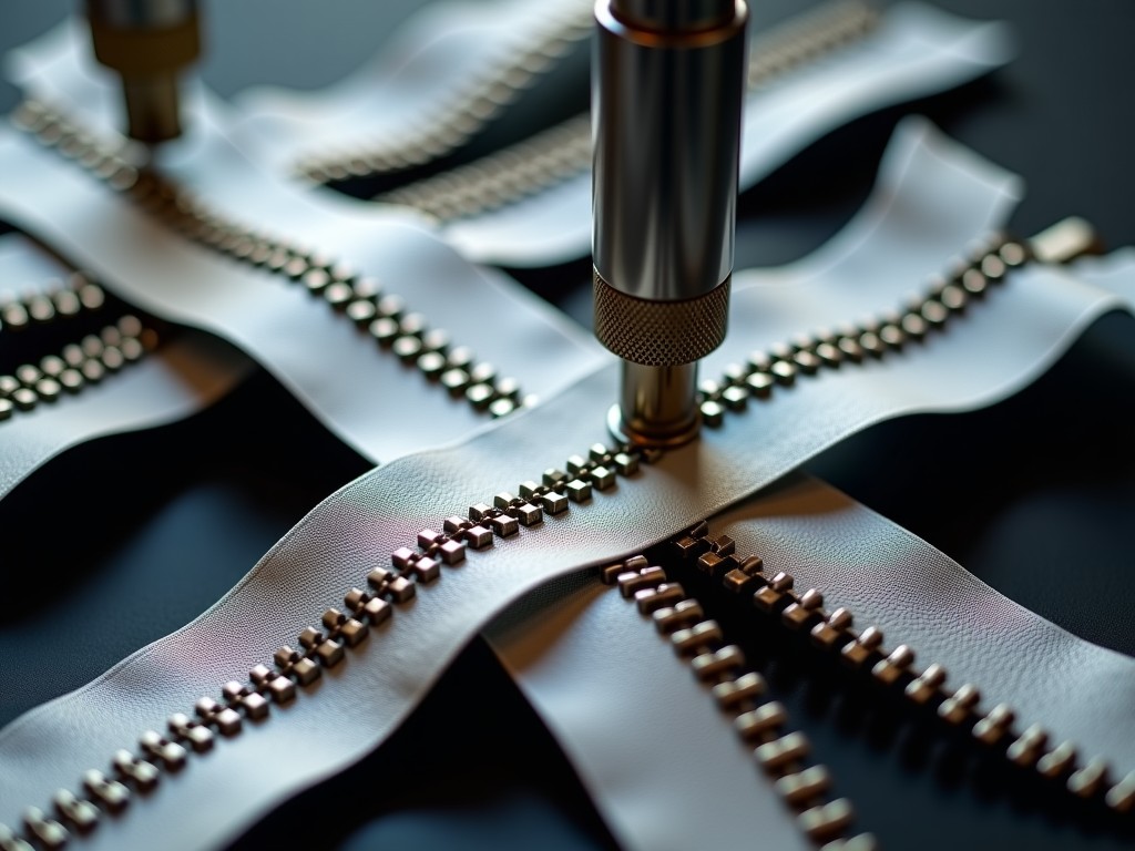
| Wire Flattening & Profiling | Rolls round wire to flat tape, then rolls tooth profile | Roll contour CNC-ground to ±0.005 mm; 2–6 stand configurations | 80–180 m/min |
| Tooth Punching & Cutting | Progressive die punches tooth shape, cuts pitch | Carbide die inserts; pitch 3.0–8.5 mm; single/double row | 200–450 strokes/min |
| Teeth Mounting (Clinching) | Presses teeth onto tape cloth/knit | Adjustable clinch force 0.8–3.5 kN; tape width 8–30 mm | 180–400 pcs/min |
| Top/Bottom Stop Assembly | Crimps metal stops onto chain ends | Stop geometry per YKK/IDE/OEM spec; auto-feed bowl | 120–300 pcs/min |
| Slider Mounting & Boxing | Inserts slider, boxes finished zipper | Slider type auto-detect; box count programmable | 60–150 pcs/min |
Modules share a common servo-driven timing bus (EtherCAT, 1 ms cycle) so speed changes propagate without mechanical re-timing. Changing from #3 to #5 nylon-coil metal zipper takes 22 minutes — die cassette swap, recipe load, and first-article gauge check.
Material Compatibility & Tooling Strategy
Metal zipper wire grades dictate die life, lubrication, and forming force. The table below summarizes typical combinations we encounter; actual tooling is specified after receiving your wire certificate and tape construction.
| Wire Alloy | Tensile (MPa) | Recommended Die Carbide Grade | Lubrication Method | Typical Die Life (strokes) |
|---|---|---|---|---|
| Brass C26000 | 350–450 | K20 micro-grain | Oil mist, 0.5 L/h | 1.2–1.8 M |
| Nickel Silver C75200 | 550–650 | K10 ultrafine | Synthetic flood, 2 L/min | 0.7–1.1 M |
| Aluminum 5052-H34 | 220–260 | K30 toughened | Dry film + air blast | 2.0–3.0 M |
| Stainless 304 (annealed) | 515–690 | K05 coated | High-pressure emulsion | 0.4–0.7 M |
Tape substrates — woven polyester, cotton/poly blend, aramid knit — affect clinch-force calibration. We supply a clinch-force map (force vs. displacement) for each tape lot during FAT, so your QC can correlate pull-test results to machine settings.
Precision Metrology & In-Process Control
Every line ships with integrated measurement stations, not as afterthoughts. A laser micrometer (±1 µm) monitors tooth height after punching; a vision system (5 MP, 0.02 mm/pixel) checks tooth symmetry and pitch accumulation at the mounting station. Data streams to a local historian (InfluxDB) and optionally to your MES via OPC UA.
If tooth height drifts beyond ±0.015 mm, the controller automatically micro-adjusts the clinch cam phase within three cycles — no operator intervention, no scrap bin filling. This closed loop is why our customers report Cpk ≥ 1.67 on critical dimensions after 30 days of production.
- First-article inspection report (FAIR) per AS9102 Form 3 included
- Gauge R&R study on height, width, pitch — GRR < 10 % target
- SPC dashboard pre-configured with your control limits
- Remote diagnostics portal (VPN, read-only) for 12 months
Typical Project Timeline — From Drawing to FAT
Lead times vary with module count and customization depth, but the phase gate structure remains consistent. We freeze design only after your sign-off on the 3D layout and Bill of Process.
| Phase | Duration (weeks) | Key Deliverables | Customer Input Required |
|---|---|---|---|
| Concept & Quotation | 1–2 | Layout sketch, module list, budgetary price | Tooth profile DXF, tape spec, annual volume |
| Detail Engineering | 4–6 | 3D model, BOM, electrical schematics, safety assessment | Approved 3D, utility specs, local code requirements |
| Fabrication & Assembly | 8–14 | Machine built, wired, preliminary run-off | Wire/tape samples for die prove-out |
| Factory Acceptance Test (FAT) | 1–2 | FAIR, SPC data, OEE ≥ 85 % at rated speed | On-site or remote witness; sign-off protocol |
| Shipment & SAT | 2–4 | Installation supervision, SAT report, operator training | Foundation ready, utilities live, raw material stocked |
A three-module line (flattening, punching, mounting) typically completes in 18–22 weeks from PO to FAT. Five-module lines with slider boxing extend to 26–30 weeks. Expedited paths exist for repeat customers with validated die libraries.
Application Fit — Where This Platform Adds Measurable Value
Apparel brands switching from purchased chain to in-house production gain control over lead time (weeks → days) and proprietary tooth profiles that differentiate product lines. Automotive seating suppliers use the same platform for high-strength nickel-silver zippers requiring 150 N crosswise strength — validated by pull-test fixtures we integrate into the mounting station.
Outdoor gear manufacturers running aluminum #5 and #8 zippers benefit from the quick-change die cassette: profile swap from 5.5 mm to 8.0 mm pitch in 18 minutes enables mixed-model scheduling without dedicated lines per size.
Contract zipper makers serving multiple OEMs leverage the recipe-driven HMI — 120 stored recipes, each locking die ID, clinch force, speed, and lubrication flow. Changeover becomes a barcode scan, not a manual setup.
Frequently Asked Technical Questions
Ready to Define Your Line Configuration?
Send us your tooth profile drawing (DXF/DWG), tape specification, target annual volume, and any existing machine constraints. We will return a preliminary layout, module recommendation, and budgetary timeline within 5 business days.
Submit Project Details for Engineering Review