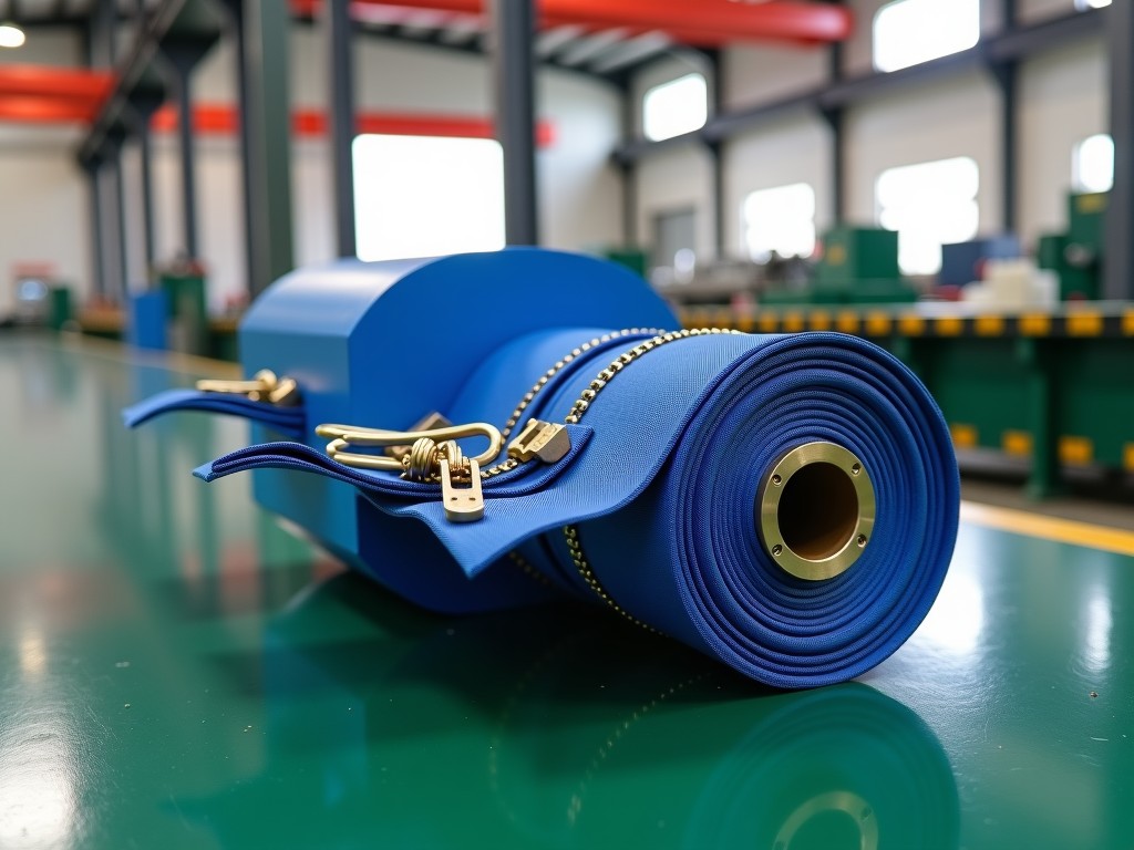
China Automatic Zipper Pin Box Machine Company
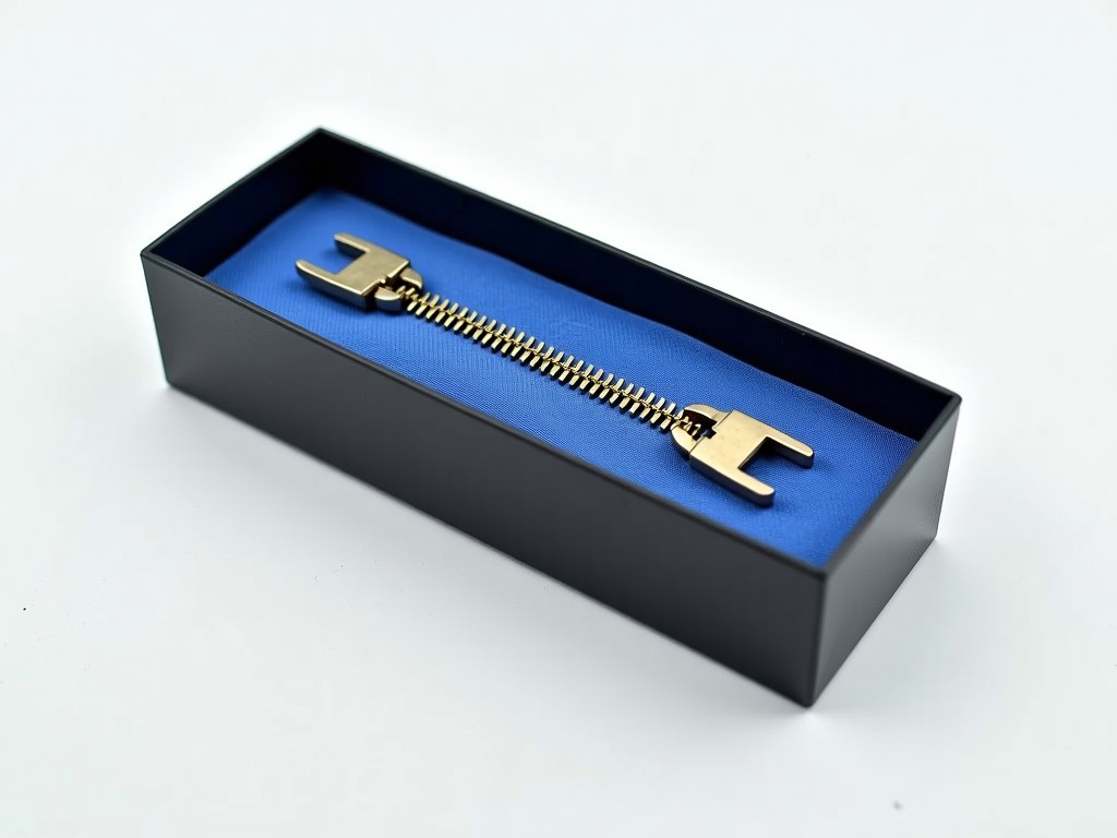
An automatic zipper pin box machine automates the high-speed assembly of pin boxes — the interlocking starter components found on separating zippers used in jackets, outerwear, and industrial textile
Automatic Zipper Pin Box Machine: Technical Overview & Manufacturing Capabilities
An automatic zipper pin box machine automates the high-speed assembly of pin boxes — the interlocking starter components found on separating zippers used in jackets, outerwear, and industrial textile products. The process integrates wire feeding, precision forming, heat treatment, and box crimping into a single continuous cycle, eliminating manual handling of small-diameter spring wire.
Equipment in this category typically operates at 120–180 pieces per minute depending on wire gauge and pin count per box. Machines designed for 4-pin and 6-pin configurations dominate standard apparel production, while 8-pin and 10-pin variants serve heavy-duty luggage and technical textile sectors. The core challenge lies in maintaining consistent pin height tolerance within ±0.05 mm across millions of cycles, which directly determines zipper engagement smoothness.
Key Technical Specifications
| Parameter | Typical Range / Configuration | Notes |
|---|---|---|
| Applicable Wire Diameter | 0.30 mm – 0.55 mm (Spring Steel / Brass) | Customizable for specialty alloys |
| Pin Count per Box | 4, 6, 8, 10 pins (Standard) | Changeover via cam set replacement |
| Production Speed | 120 – 180 boxes/min | Dependent on wire stiffness & pin count |
| Pin Height Tolerance | ±0.03 mm – ±0.05 mm | Critical for slider engagement |
| Main Drive Power | 2.2 kW – 3.7 kW (Servo or Indexer) | Servo enables recipe storage |
| Air Consumption | 0.4 – 0.6 MPa, 150 – 200 L/min | For clamping & ejection cylinders |
| Control System | PLC + HMI (Mitsubishi / Siemens / Delta) | Recipe management for multi-spec runs |
| Machine Footprint (L×W×H) | ~1,800 × 1,100 × 1,750 mm | Excludes wire payoff stand |
| Net Weight | Approx. 1,200 – 1,500 kg | Cast iron base for vibration damping |
Forming Process & Mechanical Sequence
Wire straightening precedes all forming operations. A dual-roller straightener with adjustable tension removes coil set from spring wire spools, ensuring repeatable feed length. Feed accuracy of ±0.1 mm is achieved through a servo-driven roller feed synchronized with the main camshaft encoder signal.
The forming station employs a progressive die set: the first station cuts wire to length, the second bends the U-shape, and subsequent stations form the pin legs and box crimp shoulders. Heat treatment — typically high-frequency induction heating — is integrated inline for spring steel wire to relieve bending stress and lock pin geometry. Brass wire variants skip this station, reducing cycle time by approximately 15%.
Final assembly uses a pneumatic crimp head that closes the box halves around the formed pins. Crimp force is monitored via a load cell; readings outside the 1.8–2.2 kN window trigger automatic rejection into a segregated chute. This inline check prevents loose pins that cause field failures during zipper operation.
Critical Component Engineering
Camshafts are machined from 42CrMo alloy steel, hardened to HRC 52–55, and profile-ground to IT5 tolerance. This hardness profile resists adhesive wear from high-cycle contact with roller followers. Follower rollers use bearing-grade GCr15 with crowned profiles to distribute Hertzian contact stress, extending cam life beyond 50 million cycles under normal lubrication intervals.
The crimp die inserts are fabricated from tungsten carbide (YG15 grade) for spring steel applications. Carbide withstands the abrasive wear of hardened pin tips during box closure. For brass wire lines, tool steel (Cr12MoV, HRC 58–60) offers sufficient life at lower tooling cost. Inserts are designed for quick-change via dowel-pin location, enabling pin-count changeover within 30 minutes.
Wire guide tubes and feed rollers feature ceramic (ZrO2) coatings where wire slides at high frequency. This eliminates metallic pickup and reduces feed friction coefficient to below 0.12, critical for maintaining feed accuracy on 0.30 mm diameter wire where buckling risk is highest.
Material Compatibility & Application Logic
Spring steel wire (SWPA / SWPB per JIS G 3522) remains the dominant material for mid-to-high-end apparel zippers due to its superior fatigue resistance. The machine’s induction heater is calibrated for 0.35–0.45 mm diameters typical in #3, #5, and #8 zipper sizes. Brass wire (C2680 / C2720) serves decorative and corrosion-resistant segments — marine gear, outdoor equipment — where magnetic signature or rust staining is unacceptable.
Stainless steel wire (SUS304-WPB) runs on the same platform but requires a 20% increase in crimp force and a dedicated carbide die set with polished cavities to prevent galling. Production speed typically drops 10–15% due to higher work hardening rate. Engineering teams should validate pin height stability over a 2-hour warm-up cycle, as thermal expansion in the forming dies affects tolerance holding.
Customization Parameters
- Pin count configuration: 4, 6, 8, 10, or custom patterns via modular cam sets
- Box width and height dimensions: tailored to zipper chain size (#3, #5, #8, #10)
- Wire material feed system: single spool or dual-spool auto-splicing for continuous operation
- Induction heater power: 15 kW, 25 kW, or 40 kW depending on wire gauge and line speed
- Control platform: Mitsubishi FX5U, Siemens S7-1200, or Delta DVP series per plant standardization
- Data output: OPC UA / Modbus TCP for MES integration and SPC data logging
- Safety guarding: Light curtain (Category 3, PL d) or full enclosure with interlocked doors
Quality Assurance & Inspection Protocol
First-article inspection follows a defined sampling plan: 30 consecutive boxes measured for pin height, leg length, box width, and crimp shoulder symmetry using a calibrated vision system (0.005 mm/pixel resolution). Statistical process control charts (X-bar/R) track critical-to-quality dimensions in real time; CpK ≥ 1.33 is the acceptance threshold for production release.
Functional testing mates produced pin boxes with matching slider bodies on a cyclic durability rig — 5,000 open/close cycles under 5 N lateral load. Zero pin detachment or box deformation qualifies the batch. Salt spray testing (ASTM B117, 48 hours) is available for brass and stainless variants upon customer request.
Each machine ships with a calibration certificate for the linear encoders, load cell, and induction heater power meter, traceable to national metrology standards. Spare parts kits include one full set of forming dies, two cam followers, five ceramic guide tubes, and a complete pneumatic seal kit.
Packaging, Logistics & Installation Support
Machines are secured on fumigated wooden pallets (ISPM-15 compliant) with vibration-damping mounts. Critical sub-assemblies — camshaft, servo motor, HMI panel — are individually wrapped in VCI anti-corrosion film and desiccant packs. Total shipping volume averages 4.2 CBM; gross weight 1,650 kg including packaging.
Installation requires a level concrete floor (flatness ≤ 0.5 mm/m), 3-phase 380 V / 50 Hz power with dedicated 25 A breaker, and compressed air at 0.6 MPa minimum. Commissioning typically completes in two working days: mechanical leveling, electrical hookup, parameter download, and 500-piece trial run with customer QC sign-off. Remote video guidance is available for plants with in-house millwright capability.
Frequently Asked Questions
Can the machine produce pin boxes for non-standard zipper sizes?
Yes. The forming die set and cam profile are custom-machined to your zipper chain specifications. Provide the pin box drawing or a physical sample; engineering will confirm feasibility and provide a changeover parts quotation.
What information is required for a formal quotation?
Wire material grade and diameter, pin count per box, target daily output, zipper size (#3, #5, etc.), preferred control brand, and destination voltage standard. Photos of existing pin box samples accelerate tooling design.
How is pin height consistency maintained over long runs?
Servo feed length compensation adjusts in real time based on encoder feedback from the camshaft. Thermal expansion of the forming die is offset by a temperature-compensation algorithm in the PLC when the induction heater is active. Periodic in-process gauging every 2,000 pieces is recommended.
What is the typical production lead time?
Standard configurations (4/6 pin, spring steel, Mitsubishi PLC): 45–55 working days from deposit receipt. Custom pin counts, stainless steel packages, or Siemens controls add 10–15 working days. Expedited builds may be possible depending on current shop load.
How are spare parts managed for overseas customers?
A recommended two-year spare parts list is provided with the quotation. Critical wear items (carbide dies, cam followers, ceramic guides) are stocked in standard sizes. DHL/FedEx express shipping for urgent breakdowns; sea freight for planned replenishment orders.
Can the machine integrate with an existing zipper chain assembly line?
Yes. The outfeed conveyor height and speed are adjustable to match downstream boxing or auto-packing equipment. OPC UA data exchange allows the line MES to track pin box batch ID, production timestamp, and reject counts per shift.
Request Technical Consultation
Share your wire specification, target zipper size, and daily volume requirements. Engineering will return a preliminary layout, cycle time analysis, and tooling scope within two business days.
Submit Inquiry for Zipper Pin Box Machine