Ce Certified Zipper Bottom Stop Machine Manufacturer
We design and manufacture CE certified zipper bottom stop machines for high-volume zipper tape production. Each machine integrates precision servo feeding, pneumatic clamping, and automated stop
CE Certified Zipper Bottom Stop Machine Manufacturer
We design and manufacture CE certified zipper bottom stop machines for high-volume zipper tape production. Each machine integrates precision servo feeding, pneumatic clamping, and automated stop insertion — engineered to meet EU Machinery Directive 2006/42/EC and Low Voltage Directive 2014/35/EU requirements.
Machine Architecture and Core Subsystems
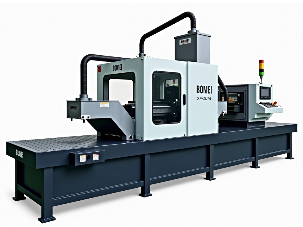
The bottom stop machine centers on a rigid cast-iron frame that absorbs vibration during the high-speed insertion cycle. A direct-drive servo feeder advances zipper tape at programmable pitch intervals — typically 3.2 mm to 6.5 mm depending on stop spacing requirements. The feeding module uses hardened steel rollers with knurled surfaces to prevent slippage on coated or waxed tapes.
Above the feed path, a pneumatic clamping station locks the tape with 0.4–0.6 MPa clamping force, adjustable via proportional valve. This force range secures lightweight nylon coil tape (35 g/m²) and heavier metal zipper tape (180 g/m²) without marking the surface. The clamping jaw profile is interchangeable — flat for standard tape, contoured for reverse-coil configurations.
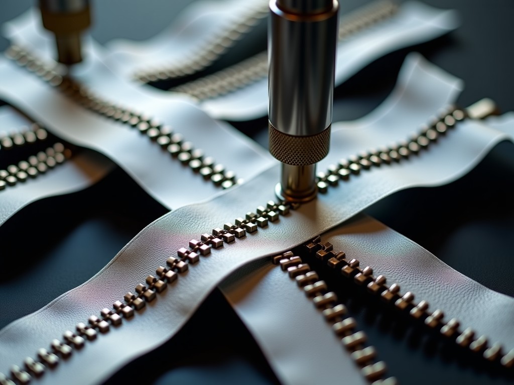
The insertion head carries a magazine-fed stop dispenser. Each cycle, a cam-driven picker extracts a single bottom stop from the magazine, positions it over the tape teeth, and presses it home with a controlled 1.2 kN forming force. A built-in force sensor verifies insertion depth — stops seated outside the 0.15 mm tolerance window trigger an automatic reject signal and cycle pause.
Technical Specifications
| Parameter | Typical Value | Notes |
|---|---|---|
| Cycle rate | 180–220 stops/min | Adjustable via HMI; limited by tape material stiffness |
| Tape width range | 10–32 mm | Quick-change guide rails, tool-less swap |
| Stop types supported | Metal (brass, aluminum), plastic (POM, PA66) | Magazine redesigned per stop geometry |
| Insertion force control | 0.8–1.5 kN, closed-loop | Force profile stored per recipe |
| Positional accuracy | ±0.1 mm | Servo encoder resolution 0.5 µm |
| Power supply | 380 VAC, 3-phase, 50/60 Hz, 4.5 kW | Complies with IEC 60204-1 |
| Compressed air | 0.6 MPa, 120 NL/min | Clean, dry air per ISO 8573-1 Class 4 |
| Machine footprint | 1,450 × 980 × 1,720 mm (L×W×H) | Excludes magazine extension |
| Weight | ≈1,350 kg | Cast iron base, steel enclosure |
CE Certification Scope and Compliance Documentation
Every machine ships with a Declaration of Conformity referencing Machinery Directive 2006/42/EC, Low Voltage Directive 2014/35/EU, and EMC Directive 2014/30/EU. The technical file — available for review by notified bodies or customs authorities — includes risk assessment per EN ISO 12100, electrical schematic per EN 60204-1, and EMC test report per EN 61000-6-2 / EN 61000-6-4.
Safety functions are implemented to Performance Level d (PL d) per EN ISO 13849-1: dual-channel emergency stop with monitored contactors, safety-rated light curtains at the feed and insertion zones, and guard-interlocked access doors with trapped-key interlocks. The safety PLC logs all safety events with timestamps for audit traceability.
Noise emission is measured per EN ISO 11202 — typical A-weighted sound pressure level at operator position is 72 dB(A) at full speed. Vibration at hand-arm contact points remains below 2.5 m/s² per EN ISO 5349-1, eliminating the need for anti-vibration gloves during normal operation.
Control System and HMI
A Siemens S7-1500 PLC coordinates motion, safety, and process logic. The 15.6" multi-touch HMI runs WinCC Unified, presenting real-time cycle count, stop insertion force trends, and OEE metrics. Operators select from up to 99 stored recipes — each recipe defines feed pitch, clamp pressure, insertion force profile, and magazine advance timing.
Remote diagnostics are standard via the integrated OPC UA server. Maintenance technicians can connect over VPN to read alarm history, force sensor calibration data, and servo drive temperature logs. Firmware updates are applied through the HMI USB port or remotely — no laptop-to-PLC cable required.
Data export supports CSV and MQTT for integration with MES or SCADA systems. Each cycle record includes timestamp, recipe ID, measured insertion force, position deviation, and pass/fail status — enabling statistical process control without additional sensors.
Changeover and Magazine Design
Changing between stop types requires swapping the magazine cassette and selecting the corresponding recipe. The cassette uses a quick-release latch — no tools — and the HMI guides the operator through a 3-minute verification cycle that confirms picker alignment, magazine sensor indexing, and force profile activation.
Magazine capacity is 2,500 stops for standard metal bottom stops (3.2 mm shank diameter). High-capacity cassettes holding 5,000 stops are available for unattended overnight runs. The magazine follower spring is calibrated per stop weight to prevent misfeeds — a common failure mode in generic vibratory bowl feeders.
Quality Inspection and Acceptance Testing
Before shipment, each machine undergoes a 4-hour run-in at the customer's specified cycle rate using their tape and stop samples. We record insertion force distribution (CpK ≥ 1.33 target), positional repeatability, and reject rate. The acceptance report includes raw data logs, not just pass/fail summaries.
Dimensional inspection of finished zipper chain samples verifies stop alignment relative to tape edge (±0.15 mm), stop leg clinch height, and absence of tape tooth deformation. For metal stops, we also measure electrical continuity across the stop — critical for conductive zipper applications in protective clothing.
Application Context: Why This Machine Fits Zipper Production Lines
Bottom stop insertion is the bottleneck in continuous zipper chain manufacturing. Manual or semi-automatic methods introduce inconsistency — stops sit crooked, legs clinch unevenly, or tape teeth deform under uncontrolled force. Our machine eliminates these variables through closed-loop force control and servo-synchronized timing.
For garment manufacturers producing waterproof zippers, the consistent clinch force ensures the stop seals against the tape coating without cracking the polyurethane layer. For luggage and outdoor gear producers running heavy-duty metal zippers, the 1.5 kN force capacity seats brass stops on #10 and #15 gauge tape without operator fatigue or repetitive strain risk.
The machine integrates upstream of the zipper chain cutting station. Its fixed pitch output matches the cutter's indexing requirement, eliminating the accumulation buffer that traditional asynchronous lines require. This reduces work-in-progress inventory by 30–40% in typical layouts.
Customization Options
- Dual-head configuration for simultaneous double-stop insertion (top + bottom) on continuous chain
- Laser marking station integrated downstream — marks batch code directly on stop shank
- Automatic tape splicing unit for reel-to-reel operation without operator intervention
- Vision inspection add-on: camera verifies stop orientation and leg clinch geometry at 200 fps
- Custom magazine geometry for proprietary stop designs — tooling lead time 3–4 weeks
- UL 508A listed electrical panel for North American installations
Maintenance Philosophy and Spare Parts Strategy
Wear parts are grouped into three maintenance kits: weekly (picker tips, clamp pads), monthly (magazine springs, proximity sensors), and annual (servo motor bearings, linear guide blocks, safety relay contacts). Each kit ships in a labeled case with QR-coded BOM linking to the digital manual.
We maintain regional spare parts depots in Shanghai, Frankfurt, and Chicago. Critical components — force sensor, safety PLC, servo drives — are stocked for 48-hour dispatch. Non-critical items ship within 5 business days. The HMI tracks operating hours and auto-generates kit replacement reminders.
Remote condition monitoring is available as an annual subscription. Vibration and current signature analysis on the feeder servo and insertion cam shaft detect bearing wear and cam follower degradation 200–300 hours before failure — enabling planned downtime instead of emergency stops.
Shipping, Installation, and Commissioning
Machines are shipped on fumigated wooden crates with vibration-damping mounts, nitrogen-purged electrical cabinets, and desiccant packs calibrated for 90-day sea freight. The crate includes fork pockets and crane lifting eyes — no special rigging required.
On-site commissioning typically requires 2 days: mechanical leveling, electrical hookup, safety validation, and recipe tuning with the customer's production tape. We provide a commissioning checklist signed by both parties. Operator training (2 shifts, up to 6 personnel) is included — covering recipe management, changeover, daily checks, and alarm response.
The standard warranty covers 12 months from acceptance or 18 months from bill of lading, whichever occurs first. Extended warranty to 36 months is available with a preventive maintenance contract.
Frequently Asked Questions
Can the machine handle both metal and plastic bottom stops on the same line?
Yes. The magazine cassette and picker head are swapped as a unit — changeover takes approximately 3 minutes. The force profile recipe adjusts automatically: metal stops typically require 1.2–1.5 kN, plastic stops 0.8–1.0 kN. The HMI prevents recipe-cassette mismatch through RFID tags on each cassette.
What information is needed for a quotation?
We require: tape material and width, stop type (metal/plastic) with dimensional drawing or sample, target cycle rate, voltage standard (380V/415V/480V), and any local certification requirements beyond CE (UL, CSA, CCC). Providing 5 meters of production tape and 500 stops allows us to run a pre-shipment validation at no charge.
How is insertion force calibrated and verified?
The force sensor (piezoelectric, 0–2 kN range, ±0.5% FS) is calibrated at our facility using a traceable load cell per ISO 376. During commissioning, we verify calibration on-site with a handheld reference sensor. The HMI includes a semi-automated recalibration routine — operators follow prompts, no external equipment needed.
What is the typical production lead time?
Standard configuration: 8–10 weeks from order confirmation to ex-works. Custom magazine tooling adds 3–4 weeks. UL 508A panel option adds 2 weeks. We provide a detailed project schedule with milestones at order acknowledgment.
Can the machine be integrated into an existing zipper line with different pitch?
Yes. The servo feeder accepts pitch commands from a master encoder or Ethernet/IP signal from the line controller. Synchronization accuracy is ±0.05 mm at 200 mm/s line speed. We supply the integration cable set and communication mapping document.
Request a technical consultation or sample validation run
Contact Our Application Engineers