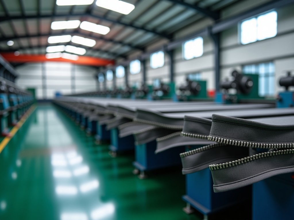
Ce Certified Complete Metal Zipper Production Line Machine Factory
A complete metal zipper production line integrates wire drawing, tape weaving, tooth forming, chain assembly, and finishing into a single synchronized system. CE certification confirms compliance
CE Certified Complete Metal Zipper Production Line Machine Factory
A complete metal zipper production line integrates wire drawing, tape weaving, tooth forming, chain assembly, and finishing into a single synchronized system. CE certification confirms compliance with Machinery Directive 2006/42/EC, Low Voltage Directive 2014/35/EU, and EMC Directive 2014/30/EU — meaning every drive, guard, and control circuit meets European safety baselines before the line leaves the factory floor.
Unlike assembled-from-stock configurations, a factory-engineered line matches motor inertias, PLC scan cycles, and tension zones across all stations. This reduces start-up scrap rates from typical 8–12% down to 2–3% in the first production week, because the tooth-forming dies and chain-assembly cams share a common timing reference rather than independent controllers.
Process Flow and Station Architecture
The line begins with a 12-station wire drawing bench that reduces Ø2.5 mm brass or aluminum wire to final tooth-profile diameter (typically Ø0.35–0.45 mm) in a single pass. Inline laser micrometers feed diameter data back to the draw-capstan VFD, maintaining ±0.005 mm tolerance — critical because a 0.01 mm oversize on the wire translates to a 0.03 mm tooth-height deviation after forming.
Tape weaving runs on 48-head needle looms with electronic let-off and take-up. Each loom produces two tapes simultaneously at 180–220 rpm, with selvedge reinforcement woven in. The take-up tension is PID-controlled from a load cell, not a spring dancer, so tape elongation stays within 0.8% even when switching between polyester and cotton blends.
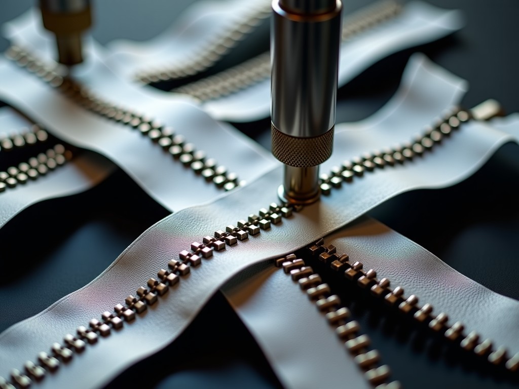
Tooth forming uses a 24-station progressive die set mounted on a servo-driven rotary indexer. The indexer dwells 180 ms per station at 120 strokes/min, giving the brass wire time to work-harden in the forming pockets. A vision system inspects every 50th tooth for profile, pitch, and burr height; out-of-spec triggers an automatic die-offset correction without stopping the line.
Technical Specifications
| Parameter | Typical Value | Notes |
|---|---|---|
| Overall line speed (chain assembly) | 120–150 m/min | Adjustable via HMI recipe |
| Wire drawing stations | 12 | Tungsten carbide dies, water-cooled |
| Needle looms | 48 heads × 2 tapes | Electronic let-off/take-up |
| Tooth forming stations | 24 progressive | Servo indexer, 180 ms dwell |
| Chain assembly heads | Dual-head, counter-rotating | Synchronized to tape feed encoder |
| Installed power | ≈ 185 kW | 380–415 V, 3-phase, 50/60 Hz |
| Compressed air | 6–7 bar, 1.2 m³/min | For pneumatic clamps and blow-off |
| Footprint (L × W × H) | 28 m × 6 m × 3.2 m | Modular, can be split for container loading |
| Control platform | Siemens S7-1500 + WinCC | Profinet backbone, 4 ms cycle |
| Safety category | Cat. 3 / PL d (EN ISO 13849-1) | Dual-channel E-stops, light curtains at all access points |
Material Compatibility and Die Selection
The line processes brass (CuZn30), aluminum (AlMgSi), and nickel-silver (CuNi18Zn20) wire. Brass remains the default for garment zippers due to its self-lubricating oxide layer; aluminum reduces weight by 65% for outdoor gear; nickel-silver provides the silver-white finish demanded by premium denim brands without plating.
Die sets are segmented: the drawing bench uses 12 interchangeable carbide nibs, while the tooth-forming module accepts 24-station cassettes that swap in 45 minutes. Each cassette carries its own RFID tag; the PLC reads the tag and loads the corresponding wire-diameter recipe, draw-speed profile, and forming-force limits. This eliminates manual parameter entry errors during changeover.
Tape materials include polyester (150–300 denier), nylon 6,6, cotton, and polyester/cotton blends. The loom's electronic let-off handles all four without mechanical gear changes — only a tension-map upload via USB. Selvedge construction varies: double-needle for polyester, single-needle with binder for cotton.
CE Certification Scope and Documentation
The Declaration of Conformity covers the complete line as a single "assembly of machinery" per Annex VII of 2006/42/EC. The technical file includes: risk assessment (EN ISO 12100), guard design calculations (EN ISO 13857), safety-related control system validation (EN ISO 13849-1), EMC test report (EN 61000-6-2/4), and electrical safety test report (EN 60204-1).
Each safety function — emergency stop, guard interlock, muting for material entry/exit — is documented with a Safety Requirement Specification (SRS) and validated by a third-party notified body. The validation report includes PL calculations, MTTFd values for each channel, and CCF analysis. This documentation ships with the line and is also stored in the HMI for on-site audit access.
For non-EU markets, the same hardware meets UL 2011 (Industrial Control Panels) and CSA C22.2 No. 301 with only the addition of UL-listed circuit breakers and NFPA 79-compliant wire colors. The PLC program includes a market-selection screen that enables/disables the relevant safety functions.
Quality Control and In-Process Inspection
Three inspection layers operate continuously. Layer 1: inline sensors — laser micrometer on wire, load cells on tape tension, force transducers on forming punches, encoder feedback on chain pitch. Layer 2: vision stations at tooth forming (profile, pitch, burr) and chain assembly (tooth alignment, tape engagement, slider clearance). Layer 3: offline sampling every 30 minutes per ISO 2859-1 AQL 1.0 for dimensional, salt-spray (ASTM B117, 96 h), and slider-pull-force (ASTM D2061) testing.
Data from all layers feeds a historian database (InfluxDB) accessible via Grafana dashboards. Operators see real-time Cp/Cpk trends per station; maintenance receives predictive alerts when forming-punch force exceeds 15% of baseline, indicating die wear. This shifts maintenance from time-based to condition-based, extending die life from 1.2M to 1.8M teeth per set.
Customization Options
- Wire diameter range: Ø0.25–0.55 mm (requires die-cassette swap)
- Tape width: 10–32 mm (loom reed change, 2-hour changeover)
- Tooth profile: Y-cut, European, corn, or custom (CAD file → EDM die)
- Chain assembly: single-track or dual-track (doubles output to 300 m/min)
- Finishing modules: ultrasonic welding, top-stop crimping, bottom-stop injection, slider mounting — selectable per order
- Control integration: OPC UA, MQTT, or Modbus/TCP for MES/ERP connectivity
Each option adds 2–4 weeks to the standard 16-week lead time. The factory runs a digital twin in Siemens Tecnomatix to validate line balance before hardware procurement begins.
Applications and Industry Fit
Apparel manufacturers running 3-shift operations benefit from the line's 150 m/min sustained speed — a single line replaces three older 50 m/min lines, cutting floorspace by 40% and labor by 60%. The servo indexer's fast changeover (45 min vs. 4 h mechanical) supports the small-lot, multi-SKU runs typical of fast-fashion supply chains.
Outdoor gear brands specify aluminum tooth lines for weight-critical products (tents, backpacks). The line's tension control prevents the tape distortion that causes aluminum teeth to bind — a common failure mode on converted brass lines where the heavier wire masks tension errors.
Automotive seating suppliers require nickel-silver zippers with 96-hour salt-spray resistance. The line's inline vision inspection catches the micro-burrs that initiate corrosion, while the historian provides lot traceability for PPAP submission.
Installation, Commissioning, and Training
The line ships in 12 pre-wired modules (max 2.4 m wide × 2.8 m high) fitting 40-ft HC containers. On-site, modules bolt together on ±2 mm shimmed pads; Profinet fiber links connect the PLC cabinets. Factory acceptance test (FAT) runs 48 hours at your specified wire/tape materials — you receive video, data logs, and signed test protocol before shipment.
Commissioning takes 5 days: mechanical alignment (day 1), servo tuning and safety validation (day 2), recipe development for your SKUs (days 3–4), and 8-hour sustained run at target OEE (day 5). Training covers operator HMI navigation, maintenance PLC diagnostics, and die-change procedures. A remote-access VPN module (TSN-enabled) allows factory engineers to assist troubleshooting within 4 hours of a support request.
Frequently Asked Questions
What information is needed for a quotation?
Wire material and diameter range, tape width and material, tooth profile type, target output (m/min), number of shifts, local voltage/frequency, and any MES integration requirements.
Can the line produce both brass and aluminum zippers?
Yes. The drawing bench and tooth-forming cassettes swap in 45 minutes. The PLC recipe system stores separate parameter sets. Tape looms require only a tension-map upload.
What is the typical production lead time?
16 weeks ex-works for standard configuration. Custom tooth profiles or dual-track assembly add 2–4 weeks. FAT adds 1 week before shipment.
How are spare parts managed?
A recommended 2-year critical spares kit (dies, punches, sensors, servo drives) ships with the line. The BOM includes manufacturer part numbers and cross-references; all components are commercially available from automation distributors.
What warranty is provided?
12 months from commissioning or 18 months from shipment, whichever comes first. Covers defects in materials and workmanship. Wear items (dies, punches, belts) excluded after 3 months.
How is the line protected for export shipment?
Modules are vacuum-sealed in VCI film with desiccant, bolted to fumigated timber skids, and braced per ISPM-15. Shockwatch and Tiltwatch indicators on each crate. Humidity data logger included for insurance claims.
Request a Technical Consultation
Share your wire specs, tape requirements, and target output. Our application engineers will return a line layout, utility summary, and budget estimate within 3 business days.
Submit Project Details