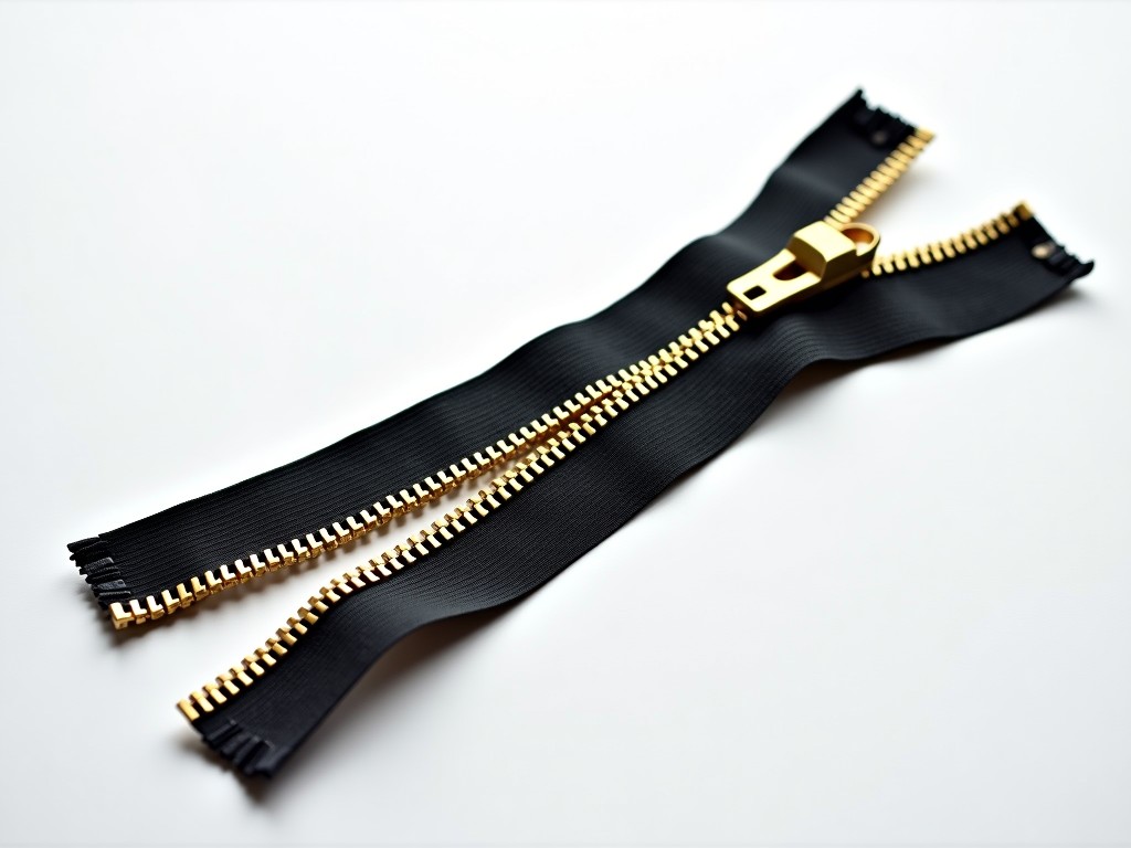
Ce Certified Brass Zipper Bottom Stop Machine Supplier
Precision forming equipment for non-ferrous zipper components with full CE conformity documentation. The machine forms brass bottom stops through a cold-heading process that compresses wire stock
CE Certified Brass Zipper Bottom Stop Machine
Precision forming equipment for non-ferrous zipper components with full CE conformity documentation.
Technical Overview
The machine forms brass bottom stops through a cold-heading process that compresses wire stock into the characteristic U-profile without material removal. This approach maintains grain structure integrity across the bend radius, which directly affects fatigue resistance during repeated zipper cycling. The forming station uses hardened tool steel dies (HRC 58-62) with polished cavities to prevent galling on soft brass alloys such as C26000 and C27000.
CE certification covers the Machinery Directive 2006/42/EC, Low Voltage Directive 2014/35/EU, and EMC Directive 2014/30/EU. The technical file includes risk assessment per EN ISO 12100, electrical schematics per EN 60204-1, and validated guard interlocking per EN ISO 14119. Declaration of Conformity and technical documentation ship with every unit.
Key Specifications
| Parameter | Typical Value | Notes |
|---|---|---|
| Forming speed | 120–180 pcs/min | Adjustable via VFD; brass wire diameter dependent |
| Wire diameter range | 0.8–1.5 mm | Standard; other sizes via die change |
| Stop profile | U-type bottom stop | Custom profiles available |
| Main motor | 2.2 kW, 3-phase, 380 V/50 Hz | Voltage configurable for target market |
| Air consumption | ~120 L/min at 0.5 MPa | For clamp actuation and parts ejection |
| Machine footprint | 1,200 × 900 × 1,650 mm | L × W × H; excludes coil payoff stand |
| Net weight | ≈ 680 kg | Cast iron base with vibration damping |
| Control system | PLC + HMI touchscreen | Mitsubishi or Siemens per customer spec |
Forming Process and Tooling
The machine feeds straight brass wire from a powered payoff stand through a straightening module (five-plane roller arrangement) before entering the forming head. A servo-driven feed mechanism positions wire to ±0.05 mm repeatability. The heading punch advances at controlled velocity — typically 40–60 mm/s during material displacement — to avoid work-hardening cracks at the inner bend radius.
Die sets are mounted on a quick-change carriage with dowel-pin location. Changeover between wire diameters requires replacing the feed rollers, straightening block, heading punch, and die cavity — approximately 25 minutes for a trained operator. Tooling material is typically D2 tool steel, cryogenically treated for dimensional stability. Carbide inserts are available for high-volume runs exceeding 50 million cycles per year.
Why This Machine Fits Zipper Component Production
Brass bottom stops endure repeated impact loading when the slider contacts the stop during closure. Cold-headed stops exhibit 30–40% higher fatigue life compared to stamped-and-bent alternatives because the uninterrupted grain flow follows the contour. The machine's consistent clamp force (adjustable 1.5–3.5 kN) prevents wire slippage during heading, eliminating the dimensional variance that causes slider snagging.
For manufacturers supplying OEM zipper tape producers, the integrated optical inspection station (optional) checks leg height, gap width, and surface defects at full production speed. Rejects divert automatically to a segregated bin without line stoppage. This capability supports the zero-defect expectations of automotive and outdoor gear supply chains.
Customization Options
- Alternative voltage/frequency: 220 V/60 Hz, 415 V/50 Hz, 480 V/60 Hz
- Carbide tooling package for extended die life
- In-line optical inspection with reject diversion
- Automatic wire splicing unit for coil changeover without stopping
- Data logging module (OPC UA) for MES integration
- Custom stop profiles: inverted-T, double-barb, or proprietary geometries
- CE + UKCA dual marking for UK market access
Quality Control and Acceptance
Each machine undergoes a 4-hour run-in at rated speed before shipment. Acceptance criteria include: dimensional CPK ≥ 1.33 on critical stop dimensions (leg height, gap width, crown radius), zero safety interlock failures over 10,000 cycles, and electrical insulation resistance > 10 MΩ at 500 VDC. Test reports accompany the shipment.
Wear parts — heading punches, die cavities, feed rollers, clamp fingers — are serialized and tracked in the maintenance manual with suggested replacement intervals based on cycle count. Spare parts kits (3-month and 12-month consumption) are quoted alongside the machine.
Packaging and Export Logistics
The machine ships on a fumigated plywood skid (ISPM-15 compliant) with vibration-damping mounts bolted to the base. Critical surfaces receive VCI anti-corrosion film; electrical cabinet is sealed with desiccant packs. Overall crate dimensions approximately 1,450 × 1,100 × 1,900 mm, gross weight ~850 kg. Suitable for 20' GP container (2 units per container with payoff stands).
Documentation package includes: commercial invoice, packing list, certificate of origin, CE Declaration of Conformity, EN 60204-1 test report, operation manual (English, Chinese, Spanish available), spare parts list with exploded views, and PLC/HMI backup files on USB.
Frequently Asked Questions
Can the stop profile be customized to our proprietary design? Yes. Provide a 2D drawing (DXF/DWG) or 3D model (STEP) with critical dimensions and tolerances. Our tooling engineers will review for cold-heading feasibility and propose die design within 3 business days.
What information is needed for a formal quotation? Wire alloy and diameter, target stop dimensions, required output (pcs/min), local voltage/frequency, and any optional modules (inspection, data logging, auto-splicing).
How is quality inspected during production? In-process: optical sensor monitors leg height and gap every cycle. Post-process: statistical sampling (AQL 1.0) on critical dimensions using calibrated vision system. Full traceability via batch QR code on each packaging box.
What is the typical production lead time? 45–60 calendar days from technical confirmation and deposit receipt for standard configuration. Custom tooling adds 15–20 days. Expedited schedules available on a case-by-case basis.
Are samples available before order placement? Yes. We can produce 500–1,000 pcs on our validation machine using your wire stock. Shipping at buyer's expense. Sample lead time: 10–15 days after receiving wire.
How are export shipments protected against humidity? VCI film wrapping, desiccant packs (calculated per crate volume), sealed electrical cabinet, and moisture indicator card inside crate for arrival verification.
Request a quotation or technical consultation for your brass zipper bottom stop production line.
Submit Inquiry →