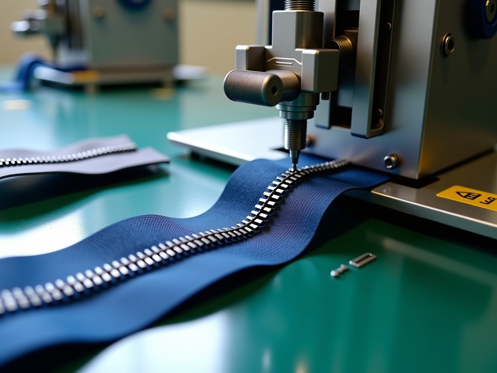
Ce Certified Automatic Zipper Making Machine Company
Machinery bearing the CE mark confirms compliance with EU Machinery Directive 2006/42/EC, Low Voltage Directive 2014/35/EU, and EMC Directive 2014/30/EU. For zipper production lines, this translates
CE Certified Automatic Zipper Making Machine Solutions
Machinery bearing the CE mark confirms compliance with EU Machinery Directive 2006/42/EC, Low Voltage Directive 2014/35/EU, and EMC Directive 2014/30/EU. For zipper production lines, this translates to validated safety circuits, guarded moving parts, and documented electromagnetic compatibility — reducing liability exposure for importers and end-users operating within the European Economic Area.
Machine Architecture and Core Subsystems
An automatic zipper making machine integrates wire feeding, tooth forming, tape weaving, and slider mounting into a synchronized continuous line. The tooth forming head — typically a multi-station rotary cam mechanism — determines pitch accuracy. Modern servo-driven cam boxes replace mechanical cams, allowing pitch changes via HMI recipe selection instead of physical gear swaps. This reduces changeover time from hours to minutes when switching between #3, #5, #8, or #10 nylon coil specifications.
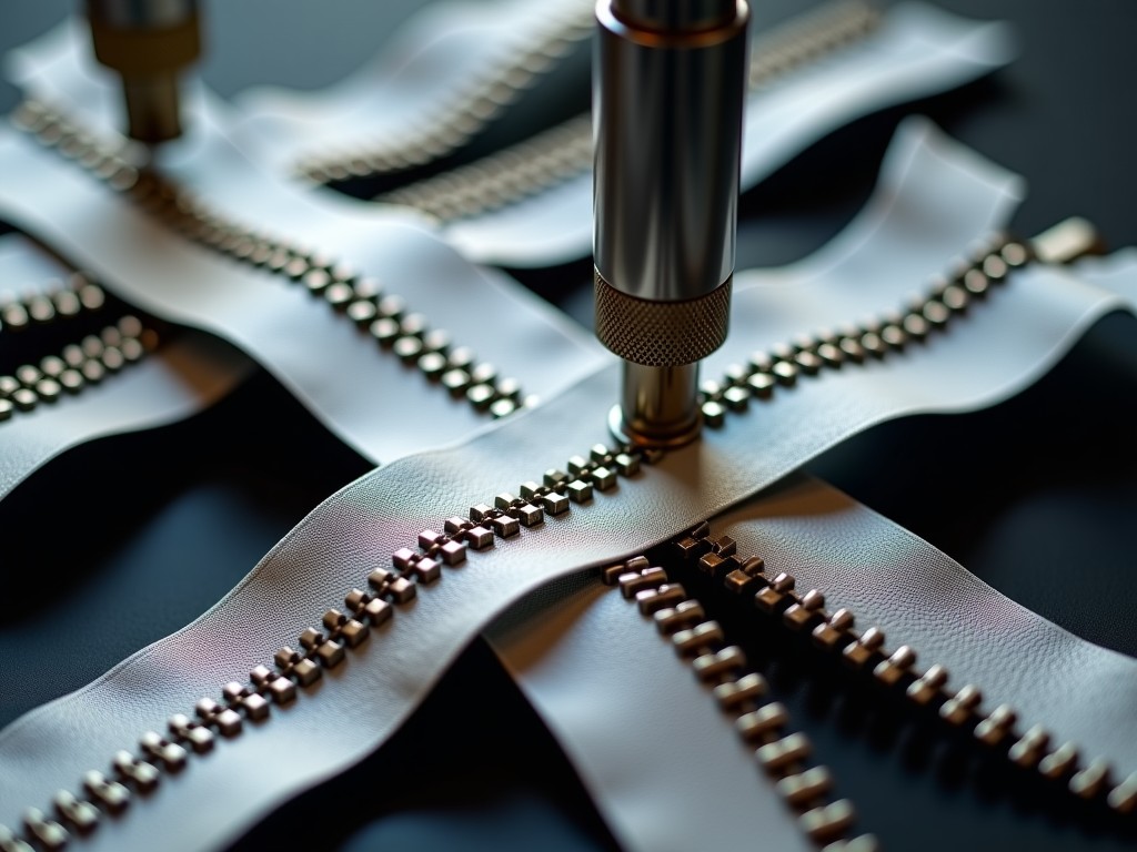
Tape feeding employs tension-controlled unwind stands with automatic splice detection. Edge guidance uses optical sensors maintaining ±0.15 mm lateral positioning, critical for preventing tooth misalignment that causes jamming during slider mounting. The welding station for metal zippers (brass, aluminum, nickel) utilizes medium-frequency inverter transformers (1–4 kHz) delivering consistent weld nugget formation across varying tape thicknesses.
CE Certification Scope for Zipper Machinery
Declaration of Conformity covers the complete assembly, not individual components. Risk assessment per ISO 12100 identifies crushing zones at the tooth forming rollers, shear points at the tape cutter, and entanglement hazards at the wire payoff. Mitigation includes Category 3 PL d safety-rated light curtains (EN ISO 13849-1) at loading zones, interlocked guards with guard-locking switches (EN ISO 14119) on forming heads, and two-hand control stations for setup mode.
Electrical equipment follows EN 60204-1: control circuits at 24 VDC, main power with residual current monitoring, and emergency stop circuits hardwired to Safety PLC (not software-only). EMC testing per EN 61000-6-2/4 ensures immunity to conducted/radiated disturbances from nearby welding equipment — common in zipper factories where high-frequency welders operate alongside sensitive servo drives.
Technical Parameter Reference
Values below represent typical ranges for standard nylon coil and metal zipper lines. Final specifications are configured per project requirements — tape width, tooth profile, output speed, and automation level.
| Parameter | Nylon Coil Line (Typical) | Metal Zipper Line (Typical) | Customization Notes |
|---|---|---|---|
| Applicable Zipper Sizes | #3, #4, #5, #6, #8, #10 | #3, #4, #5, #8, #10 | Die sets swapped per size; multi-size quick-change available |
| Tooth Pitch Range | 2.2–4.5 mm (servo adjustable) | 3.0–6.5 mm (servo adjustable) | Recipe stored in HMI; no mechanical gear change |
| Production Speed | 120–220 m/min | 80–150 m/min | Dependent on tooth profile, tape material, weld/cooling time |
| Tape Material Compatibility | Polyester, cotton, blended, water-repellent | Polyester, cotton, aramid-reinforced | Tension profiles programmable per material batch |
| Wire/Tooth Material | Nylon 66 monofilament (0.25–0.35 mm) | Brass, aluminum, nickel-silver wire (0.3–0.5 mm) | Wire payoff tension controlled to ±5 g |
| Main Drive Power | 18–35 kW (servo motors) | 25–45 kW (servo + welding inverter) | Energy recovery on deceleration optional |
| Compressed Air Consumption | 0.6–1.2 m³/min @ 0.6 MPa | 1.0–2.0 m³/min @ 0.6 MPa | Air dryer and filter regulator included in scope |
| Line Footprint (L×W×H) | 12–18 m × 2.5–3.5 m × 2.2 m | 15–22 m × 3.0–4.0 m × 2.5 m | Modular layout; can be split for container shipping |
| Control System | Siemens S7-1500 / Beckhoff CX / B&R X20 | Same platforms; Safety PLC integrated | OPC UA / MQTT / Profinet for MES connectivity |
| HMI Interface | 15–21 inch multi-touch, multi-language | Same; recipe management with version control | Remote access via VPN gateway (optional) |
Automation Levels and Integration Options
Standalone tooth forming machines suit job shops producing diverse short runs. Fully automatic lines integrate: automatic bobbin changers (reducing wire reload downtime to <30 seconds), inline quality inspection cameras measuring tooth height, pitch, and tape edge position at 100% throughput, and automatic cut-to-length with stacking conveyors. For metal zippers, automatic slider mounting cells — robotic pick-and-place with vision-guided alignment — achieve 120–180 pieces/minute with <0.5% defect rate.
MES integration via OPC UA enables real-time OEE tracking: availability losses categorized by changeover, micro-stops, speed loss; quality losses by defect code. This data drives preventive maintenance schedules — e.g., tooth forming roller replacement triggered by cumulative meter count rather than fixed calendar intervals.
Material Handling and Consumable Management
Wire payoff stands accommodate 5–25 kg spools with active dancer-arm tension control. For high-volume lines, rotary magazine payoffs hold 8–12 spools, enabling automatic splicing without line stop. Tape creels use motorized unwind with edge-guide sensors; splice detection triggers automatic slowdown and marker insertion for downstream removal. Lubrication systems — centralized progressive distributors — deliver metered oil to cam followers, needle bearings, and gear meshes at programmable intervals, monitored by flow sensors feeding PLC alarms.
Quality Assurance and Acceptance Testing
Factory Acceptance Test (FAT) protocol includes: no-load run-in (8 hours) verifying vibration spectra <2.5 mm/s RMS on forming heads; loaded production run (4 hours) at rated speed measuring tooth pitch CpK >1.33 across 500 consecutive teeth; safety function verification — light curtain response time, E-stop Category 0/1 compliance, guard interlock defeat testing. Site Acceptance Test (SAT) adds tape material validation with customer-supplied batches.
Documentation package delivered with each line: CE Declaration of Conformity, technical file per Annex VII Machinery Directive, electrical schematics (EPLAN), pneumatic diagrams, PLC/HMI source code (password-protected), maintenance manual with lubrication charts and spare parts BOM (Level 1: 2-year recommended stock; Level 2: 5-year).
Shipping, Installation, and Commissioning
Lines ship in modular sections: forming head module, tape feeding module, welding/slider module, control cabinet. Each module mounted on machined base frames with leveling feet (±5 mm adjustment). Critical alignments — forming head to tape guide, welding electrode to tooth gap — preset at factory with laser alignment reports. On-site commissioning typically 5–10 days depending on automation level; includes operator training (mechanical adjustment, HMI operation, basic troubleshooting) and maintenance technician training (servo tuning, safety system diagnostics, predictive maintenance setup).
After-Sales Support Structure
- Remote diagnostics via secure VPN — 4-hour response during business hours, 24/7 for critical safety faults.
- Spare parts warehouse: forming rollers, cam followers, servo motors, welding electrodes, safety sensors — typical lead time 3–5 business days for standard items.
- Annual calibration service: pitch accuracy verification, welding parameter validation, safety function re-test.
- Retrofit packages: servo upgrade for legacy mechanical cam machines; safety system modernization to current PL d/e standards.
Frequently Asked Technical Questions
Can the machine produce both nylon coil and metal zippers on the same line?
Dedicated lines are recommended. Nylon coil forming uses rotary needle heads; metal zipper forming uses die-stamping/welding heads. Mechanical architecture, lubrication requirements, and safety zoning differ significantly. A convertible platform exists but adds 35–40% capital cost and 2–3 hour changeover — only justified for very low volumes of each type.
What information is required for a detailed quotation?
Zipper type (nylon coil / metal / invisible), size range (#3–#10), target daily output (meters or pieces), tape material specs, automation level (standalone / semi-auto / fully automatic with inspection), factory layout constraints (ceiling height, column spacing, power supply voltage/phase), and local regulatory requirements beyond CE (e.g., NR-12 for Brazil, OSHA for USA).
How is tooth pitch accuracy maintained over long production runs?
Servo-driven cam boxes with absolute encoders eliminate mechanical backlash. Closed-loop pitch control uses inline optical encoder on tape feed measuring actual pitch every tooth; PLC adjusts cam phase in real-time (±0.02 mm correction). Thermal expansion compensation: forming head temperature monitored via embedded RTDs; pitch offset table applied automatically.
What are the typical wear parts and replacement intervals?
Forming rollers (carbide-coated): 8–12 million teeth. Cutting blades: 5–8 million cuts. Welding electrodes (metal lines): 200–400k welds depending on wire material. Needle bearings in cam followers: 15,000–20,000 hours. All intervals tracked in PLC with predictive alerts at 80% life.
How are export shipments protected for sea freight?
Modules vacuum-sealed in VCI (volatile corrosion inhibitor) barrier bags with desiccant calculated per DIN 55474. Machined surfaces coated with removable rust preventive. Shock/tilt indicators (SpotSee ShockWatch) affixed to each crate. Fumigation-free plywood crates per ISPM-15. Humidity data loggers included for transit monitoring.
What is the typical production lead time after order confirmation?
Standard nylon coil line: 90–120 working days. Metal zipper line with welding: 110–140 working days. Fully automatic line with inspection and slider mounting: 140–180 working days. Lead time starts upon receipt of advance payment and approved electrical/pneumatic schematics. Critical path items: servo motor/drive delivery (12–16 weeks), safety PLC (8–10 weeks).
Request Technical Consultation
Share your zipper specifications, target output, and facility constraints. Our application engineers will provide a preliminary layout, utility requirements, and budget indication within 3 business days.
Submit Project Requirements