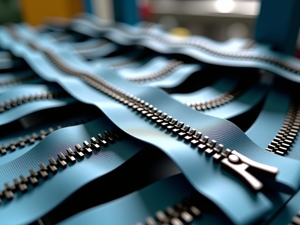
Ce Certified Automatic Metal Zipper Production Line
Modular high-speed line for continuous metal zipper chain manufacturing with integrated quality monitoring and CE conformity declaration. This production line integrates wire drawing, teeth forming,
CE Certified Automatic Metal Zipper Production Line
Modular high-speed line for continuous metal zipper chain manufacturing with integrated quality monitoring and CE conformity declaration.
Technical Overview
This production line integrates wire drawing, teeth forming, tape feeding, teeth mounting, and chain inspection into a single synchronized system. The architecture separates mechanical motion control from process parameter management, allowing operators to adjust tooth pitch, tape tension, and mounting pressure without mechanical changeovers. Typical output ranges from 180 to 240 meters per minute depending on tooth profile and material combination.
The line handles brass, aluminum, and nickel-silver wire diameters from 0.25 mm to 0.45 mm. Tape width accommodation spans 10 mm to 25 mm (standard #3, #4, #5, #7, #8 sizes). All servo axes synchronize through a EtherCAT backbone with cycle time under 1 ms, ensuring tooth-to-tape registration within ±0.05 mm at full speed.
CE certification covers Machinery Directive 2006/42/EC, Low Voltage Directive 2014/35/EU, and EMC Directive 2014/30/EU. The declaration of conformity references EN ISO 12100, EN 60204-1, and EN 61000-6-2/6-4. Safety circuits implement Category 3 PL d per EN ISO 13849-1 with dual-channel emergency stop monitoring and light curtain guarding at all access points.
Key Technical Specifications
| Parameter | Standard Configuration | Customizable Range |
|---|---|---|
| Max line speed | 240 m/min | 180–260 m/min (profile dependent) |
| Wire diameter | 0.25–0.45 mm | 0.20–0.50 mm |
| Tape width | 10–25 mm | 8–30 mm |
| Tooth pitch accuracy | ±0.05 mm | ±0.03 mm (with closed-loop vision) |
| Mounting force control | Servo-driven, 0–500 N | 0–800 N with force profile logging |
| Power supply | 380 VAC, 3-phase, 50/60 Hz | 220–480 VAC per local grid |
| Compressed air | 0.6 MPa, 150 L/min | 0.5–0.7 MPa per plant supply |
| Line footprint (L×W×H) | 12 m × 2.8 m × 2.2 m | Modular, configurable per layout |
| Control platform | Beckhoff CX2040 + EtherCAT I/O | Siemens, Mitsubishi, or B&R on request |
| HMI | 15.6" capacitive multi-touch, IP65 | 19" or 21.5", VNC remote access option |
Values represent typical configurations. Final specifications confirmed during technical consultation based on tooth profile, material, and throughput targets.
Core Module Engineering
Wire Drawing & Straightening Unit
Four-stand tandem drawing with individual servo tension control reduces work hardening variation. Carbide dies (Grade K10–K20) provide 50,000 m typical life before regrind. In-line laser micrometer measures diameter at 1 kHz sampling; data feeds forward to teeth forming servo compensation. Straightening rolls use polyurethane-coated steel to prevent surface marking on soft alloys.
Teeth Forming Head
Rotary cam-driven forming with 12-station tooling carousel. Each station independently adjustable for tooth height, width, and flank angle. Quick-change tooling blocks mount on repeatable kinematic couplers — changeover under 15 minutes. Forming force monitored via piezoelectric load cells; deviations beyond ±3% trigger automatic reject gate. Tool steel (D2, HRC 58–60) yields 2–3 million teeth per set depending on wire hardness.
Tape Feeding & Tension System
Dual servo-driven nip rollers with dancer arm accumulator absorb splice transitions without speed disturbance. Tension control loop updates at 2 kHz using load cell feedback. Edge guide uses pneumatic side-lay with optical edge detection (±0.1 mm). Tape spool capacity 5,000 m; automatic splicing station optional for continuous operation.
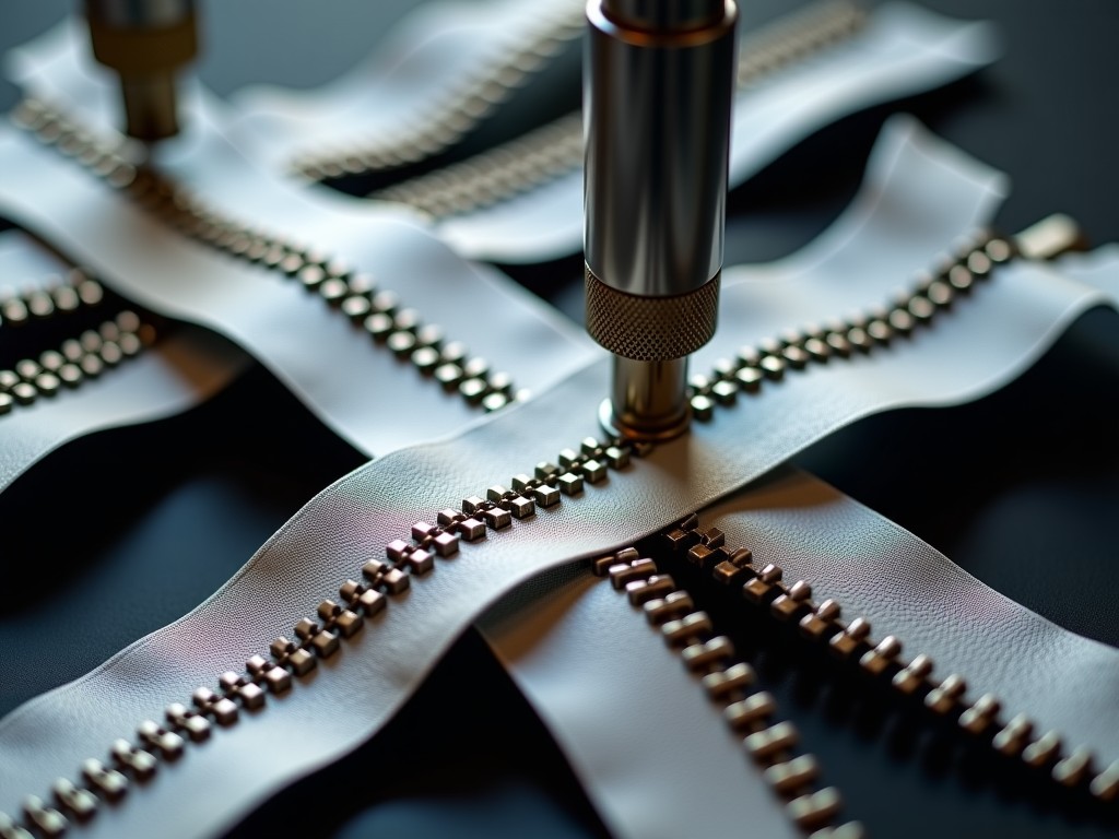
Teeth Mounting & Clinching Station
Servo-electric clinching heads replace traditional cam mechanisms. Force-displacement curves recorded for every tooth; data stored for traceability. Clinching profile programmable per tooth type — Y-cut, box, or European profile. Anvil and clincher tools hardened to HRC 62; typical life 1.5 million cycles. Missing-tooth detection via through-beam sensors at 99.99% reliability.
Vision Inspection & Reject System
Dual-camera line-scan system (2K resolution, 40 kHz line rate) inspects tooth geometry, tape alignment, and clinch quality. Inspection criteria configurable via HMI recipe management. Reject mechanism uses pneumatic pusher with 5 ms response; rejected segments collected in segregated bin with timestamp logging. False reject rate under 0.02% at 200 m/min validated on brass #5 chain.
Application Fit by Industry
Garment manufacturers running #3–#5 brass zippers benefit from the line's quick-change tooling — style changes between jean, jacket, and dress zippers complete in under 20 minutes. The force-displacement logging satisfies brand audit requirements for clinch integrity traceability.
Outdoor gear and military spec producers use the nickel-silver capability with closed-loop vision. The ±0.03 mm pitch accuracy meets MIL-DTL-32075 tooth spacing tolerances. Servo clinching force profiles accommodate the higher work hardening of nickel-silver without tape damage.
Automotive seating suppliers running #8–#10 aluminum chain appreciate the 260 m/min upper speed range and automatic splicing. The line's EtherCAT backbone integrates with plant MES for OEE tracking and predictive maintenance triggers based on forming force trends.
Luggage and bag factories value the modular footprint — the mounting station can be duplicated for double-chain output without lengthening the line. Tape width range up to 30 mm covers heavy-duty coil-to-metal transition zippers.
CE Conformity & Safety Architecture
The technical file includes risk assessment per EN ISO 12100 covering mechanical, electrical, thermal, and noise hazards. All moving parts with injury potential are guarded by fixed enclosures with interlocked access doors (coded magnetic switches, Category 4). Light curtains (Type 4, SIL 3) protect the forming and mounting zones where operator access is required for tooling changes.
Electrical enclosure rated IP54 with UL 508A listed components. Emergency stop circuit uses safety relay with cross-circuit monitoring; reset requires deliberate dual-action (pull E-stop, then press illuminated reset). Stored energy dissipation — pneumatic dump valves, servo drive DC bus discharge — verified to under 5 seconds.
Noise emission measured at operator position: 78 dB(A) at 200 m/min per EN ISO 11202. Vibration at hand-arm contact points below 2.5 m/s² per EN ISO 5349. Both values documented in the declaration of conformity.
Documentation package delivered with each line: Declaration of Conformity (EU/UK), technical file index, electrical schematics (EPLAN), pneumatic diagrams, safety circuit validation report, noise/vibration test report, and operator/maintenance manuals in English (other languages on request).
Customization Options
The modular frame design allows configuration at order stage without structural redesign. Common customizations include:
- Dual mounting heads for simultaneous double-chain production (adds 0.8 m line length)
- Automatic tape splicing unit with ultrasonic weld for continuous 24/7 operation
- Inline lubrication system (micro-dosing, 0.01 mm³ per tooth) for high-speed aluminum
- Extended vision inspection: 360° tooth surface scan for cosmetic defect detection
- MES integration package: OPC UA server, SQL logging, digital twin data stream
- Cleanroom-compatible version (ISO Class 7) with stainless enclosures and HEPA filtration
- Alternative control platforms: Siemens S7-1500, Mitsubishi MELSEC iQ-R, B&R X20
Each customization undergoes the same CE re-assessment process. Lead time impact typically 4–8 weeks depending on complexity.
Quality Control & Acceptance Testing
Factory acceptance test (FAT) protocol runs 8 hours at rated speed with customer-specified wire and tape. Measured parameters: tooth pitch distribution (CpK ≥ 1.33), clinch force CpK ≥ 1.67, missing tooth detection rate, false reject rate, and OEE components. Test data provided in CSV format with statistical summary.
Site acceptance test (SAT) after installation includes safety function verification, communication integration check, and 4-hour production run with customer materials. Operator training (16 hours standard) covers recipe management, tooling changeover, preventive maintenance schedules, and fault diagnosis using HMI diagnostic screens.
Spare parts kit shipped with line includes: forming tool set (1), clincher/anvil set (2), drawing die set (1), critical sensors (2 each), safety relay (1), servo drive module (1), and 12-month consumables forecast. Recommended spares list customized per shift pattern and annual volume.
Frequently Asked Questions
Can the line produce both Y-cut and European profile teeth?
Yes. The 12-station tooling carousel accommodates mixed profiles. Recipe selection loads the forming cam profile, clinching force curve, and vision inspection criteria simultaneously. Changeover between profiles requires tooling block swap (15 min) and recipe load (30 sec).
What information is needed for a quotation?
Tooth profile drawings or samples, wire material and diameter, tape material and width, target daily output, shift pattern, local voltage/frequency, compressed air availability, and any MES integration requirements. Layout drawings of the installation space help identify footprint constraints early.
How is clinch quality validated during production?
Every clinch cycle records force vs. displacement at 10 kHz sampling. The curve is compared against the master reference envelope (±5% tolerance). Deviations flag the specific tooth for vision re-inspection and automatic segregation. Data exports via OPC UA for statistical process control.
What is the typical production lead time?
Standard configuration: 16–20 weeks from order confirmation to FAT. Customized lines: 22–28 weeks depending on control platform and automation level. Shipping, installation, and SAT add 3–4 weeks.
How are export shipments protected?
Modules shipped in fumigated wooden crates (IPPC marked) with vacuum-sealed barrier bags and desiccant for corrosion protection. Shock indicators (3-axis, 5G threshold) attached. Critical alignment surfaces coated with VCI oil. Lifting points marked and load-tested.
Can we run sample trials before ordering?
Trial runs available at our technical center in Ningbo with customer materials. Typical trial: 2–3 hours covering setup, speed ramp, and quality sampling. Trial report includes all measured parameters. Remote witnessing via live stream supported.
Request Technical Consultation
Share your tooth profile, material specs, and volume targets. We'll return a preliminary layout, cycle time analysis, and budget indication within 5 business days.
Start Technical Discussion