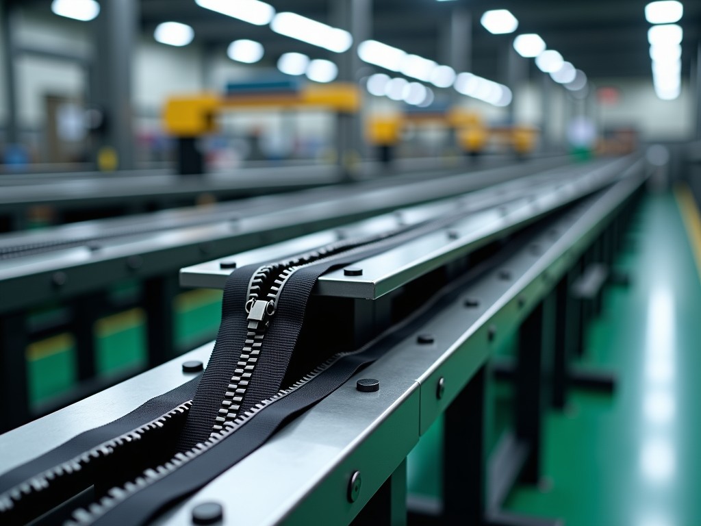
Automatic Metal Zipper Production Line Company
Metal zipper manufacturing requires precise coordination between tape feeding, tooth forming, clamping, and cutting operations. An automatic production line integrates these stages into a continuous
Automatic Metal Zipper Production Line
Metal zipper manufacturing requires precise coordination between tape feeding, tooth forming, clamping, and cutting operations. An automatic production line integrates these stages into a continuous flow, reducing manual intervention while maintaining the dimensional tolerances necessary for consistent zipper function.
This page outlines the technical architecture, process capabilities, and selection criteria for fully automatic metal zipper production lines. Information is structured for procurement engineers, production managers, and OEM buyers evaluating capital equipment investments.
Line Architecture and Process Flow
A complete automatic metal zipper production line typically comprises five primary modules arranged in series: tape unwinding and tension control, wire feeding and straightening, tooth forming and clamping, top/bottom stop attachment, and finished zipper cutting with stacking. Each module operates under PLC control with servo-driven actuators to maintain synchronization at speeds ranging from 80 to 180 meters per minute depending on tooth profile and material.
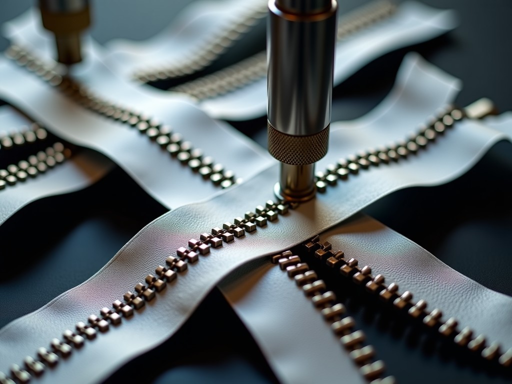
Tape tension is managed through dancer rollers coupled with load cells, maintaining variation within ±3% of setpoint. Wire feed uses straightening rollers preceded by a pay-off stand with pneumatic braking to prevent overrun during acceleration cycles. The forming station employs hardened tool steel dies — typically H13 or D2 heat-treated to 58–62 HRC — shaped to the specific tooth profile (Y-cut, European, or custom geometry). Clamping force is monitored in real time via piezoelectric sensors, with automatic compensation for tool wear.
Stop attachment uses vibratory bowl feeders oriented by vision inspection to ensure correct orientation before ultrasonic welding or mechanical crimping. The cutting module incorporates a flying shear mechanism synchronized to line speed, eliminating start-stop cycles that cause tape distortion. Finished zippers are stacked by a robotic pick-and-place unit programmable for batch quantities from 50 to 500 pieces.
Technical Specifications
| Parameter | Typical Range | Notes |
|---|---|---|
| Production speed | 80–180 m/min | Dependent on tooth size and wire diameter |
| Tooth pitch | 2.5–6.0 mm | Custom pitches available via die change |
| Wire diameter | 0.25–0.45 mm | Brass, copper, or aluminum alloy |
| Tape width | 10–30 mm | Polyester, cotton, or blended substrates |
| Clamping force repeatability | ±2.5% | Monitored per tooth via force sensor |
| Length cutting tolerance | ±0.5 mm | At 100 m/min line speed |
| Power consumption | 18–35 kW | Varies with line configuration |
| Compressed air requirement | 0.6–0.8 MPa, 300–500 NL/min | Clean, dry air per ISO 8573-1 Class 4 |
| Footprint (L×W×H) | 12–18 m × 2.5 m × 2.2 m | Modular layout adaptable to factory floor |
| Control system | Siemens S7-1500 / Beckhoff CX series | OPC UA and Profinet standard |
Critical Subsystems and Engineering Considerations
Die life directly impacts operating cost. Forming dies for brass wire typically achieve 8–12 million teeth before regrinding, while copper alloy wire reduces die life by 30–40% due to higher adhesion tendency. Die changeover time averages 45 minutes with quick-clamp mounting; lines equipped with die libraries and automatic alignment reduce this to under 15 minutes.
Tape guide rails are ceramic-coated to minimize friction-induced tape heating, which otherwise causes width shrinkage and misaligned teeth. Guide gap adjustment is motorized with 0.01 mm resolution, stored in recipe files per tape batch. This eliminates manual shimming and reduces setup scrap from 200–300 meters to under 50 meters per changeover.
Wire tension control uses a closed-loop dancer with inertia compensation. At line speeds above 150 m/min, wire vibration between straightener and forming die becomes a defect source — tooth tilt and missing teeth increase nonlinearly. Active damping rollers with piezoelectric actuators suppress this vibration, maintaining tooth perpendicularity within 0.15°.
Material Compatibility and Selection Logic
Wire material selection balances cost, corrosion resistance, and forming behavior. Brass (CuZn30) remains the industry standard for apparel zippers — good formability, adequate strength, and acceptable salt spray performance (72 hours per ASTM B117). For outdoor gear and marine applications, nickel-silver (CuNi18Zn20) extends salt spray to 200+ hours but requires 15% higher clamping force and reduces die life.
Aluminum alloy wire (AlMgSi) reduces weight by 65% versus brass, used in lightweight technical apparel. However, its lower modulus increases springback, requiring die geometry compensation of 0.03–0.05 mm per tooth flank. Oxide layer formation on aluminum wire mandates in-line cleaning brushes and anti-oxidant coating applicators to prevent galling in forming dies.
Tape substrate affects tooth adhesion. Polyester tape with 15–20% polyurethane coating provides optimal mechanical interlock with clamped teeth. Cotton tape requires higher clamp force (25% increase) and often exhibits tooth slippage after repeated wash cycles. Blended tapes (polyester/cotton 65/35) offer a compromise but require validated clamp recipes per batch.
Quality Inspection Integration
In-line inspection stations are positioned at three points: post-forming (tooth geometry), post-stop attachment (stop position and weld integrity), and post-cutting (length and end condition). Each station uses telecentric lenses with 5 µm/pixel resolution and structured light for 3D tooth height measurement.
Inspection criteria include tooth height (±0.03 mm), tooth pitch (±0.02 mm), clamp mark depth (0.08–0.12 mm), stop position (±0.3 mm), and cut end squareness (≤0.2 mm deviation). Defective zippers are diverted automatically via pneumatic pushers into segregated bins. Statistical data logs are stored for 12 months with traceability to wire lot, tape roll, and die set.
Offline sample testing follows ASTM D2061 for zipper strength and ASTM D3654 for durability cycling. A typical qualification run produces 5,000 cycles at 30 cycles/minute under 5 kg transverse load. Lines commissioned with integrated inspection typically achieve first-pass yield above 98.5% after recipe stabilization.
Customization Options
- Tooth profile dies: Y-cut, European, corn-tooth, or custom geometry per customer specification
- Stop type: Top stop only, bottom stop only, or both; open-end or closed-end configurations
- Tape edge finish: Ultrasonic sealed, hot-cut, or folded-under for fray prevention
- Color sorting: Inline spectrophotometer for tape color verification against L*a*b* tolerances
- Packaging: Bulk stack, individual polybag, or reel winding with programmable length per reel
- MES integration: SAP, Siemens Opcenter, or custom API via OPC UA / MQTT
Installation, Commissioning, and Training
Installation requires a level concrete floor with flatness tolerance of 5 mm over 3 m. Anchor bolts are M16 chemical anchors at 800 mm spacing. Power supply must be 380–415 VAC, 3-phase, 50/60 Hz with dedicated circuit and <2% voltage unbalance. Compressed air connection at line inlet with 1 µm filtration and refrigerated dryer.
Commissioning spans 5–7 working days: mechanical alignment (day 1), electrical and pneumatic hookup (day 2), servo tuning and sensor calibration (day 3), recipe development for customer materials (days 4–5), and production validation run (days 6–7). Validation run targets 8 hours continuous operation at rated speed with first-pass yield ≥97%.
Operator training covers HMI navigation, recipe management, die change procedure, sensor cleaning, and basic troubleshooting. Maintenance training includes preventive maintenance schedules (daily, weekly, monthly), lubrication points with specified greases (Klüberplex BEM 41-132 for linear guides, Mobilith SHC 220 for gearboxes), and spare parts identification. Documentation package includes electrical schematics, PLC program backup, mechanical drawings, and BOM with manufacturer part numbers.
Frequently Asked Questions
Can the line produce multiple tooth sizes on the same equipment?
Yes. Die sets are interchangeable. Changing from #3 to #5 tooth pitch requires die replacement, guide rail adjustment, and recipe selection — typically 45 minutes with standard tooling, 15 minutes with quick-change die library. Wire straightener rollers may require swap for diameters differing by more than 0.05 mm.
What information is needed before a formal quotation?
Required: target tooth profile and pitch, wire material and diameter, tape material and width, desired production speed (m/min), stop configuration (open/closed end), annual volume estimate, and factory floor layout constraints. Optional but helpful: existing zipper samples, quality acceptance criteria, and MES integration requirements.
How is color consistency managed across production batches?
Tape color is verified at unwind station via inline spectrophotometer measuring L*a*b* at 10 mm intervals. Deviations beyond ΔE 1.0 trigger alarm and automatic line slowdown. For multi-color runs, recipe files store target values per color code. Tape supplier batch certificates are cross-referenced during incoming inspection.
What are the typical lead times for delivery and commissioning?
Standard configuration (single tooth size, brass wire, polyester tape): 16–20 weeks ex-works. Custom die development adds 3–4 weeks. Commissioning at customer site: 5–7 working days plus travel. Expedited schedules possible with parallel engineering — discuss with project management team.
What spare parts package is recommended for the first two years?
Critical spares: 2 forming die sets, 1 clamp die set, 50 ceramic guide inserts, 10 wire straightener rollers, 5 force sensors, 3 vision camera modules, 1 servo motor per axis type, 1 PLC CPU, 1 HMI panel, pneumatic valve manifold, and 200 m tape guide belts. Consumables: lubrication greases, filter elements, and cleaning swabs per maintenance schedule.
How are export shipments protected?
Modules are shipped in seaworthy wooden crates with vacuum-sealed barrier bags containing desiccant (silica gel, 2 kg/m³). Machined surfaces coated with VCI anti-corrosion oil (Cortec VCI-369). Shock and tilt indicators attached. Lifting points marked per ISO 780. Container loading supervised with photographic documentation at each stage.
Can samples be produced before purchase commitment?
Sample runs are conducted at our technical center using customer-supplied wire and tape (minimum 5 kg wire, 200 m tape). Output: 500–1,000 zippers across speed range with full inspection reports. Sample testing fees are credited against equipment purchase order. Remote witnessing via live video stream available.
Ready to discuss your metal zipper production requirements?
Provide your tooth profile, material specs, and target volume. We will return a detailed technical proposal with layout drawings, utility requirements, and investment breakdown within 5 business days.
Request Technical Proposal